Making a mixer with your own hands
The mixing console is designed to mix multiple audio signals. For example, it is used if you want to sound an amateur film, or you need a voice accompaniment of a disco, for tour guides, for karaoke, to connect a musical instrument to a computer, etc. The mixer is used for recording and for concerts, when the sound engineer needs to set the optimal sound parameters for the hall. Based on the foregoing, it is clear that this unit is indispensable, and its use is multifaceted.
On sale there are a huge number of models, both for professionals and for ordinary users. But for beginning musicians or just karaoke lovers, prices for audio equipment seem high enough. Therefore, for home use mixer can be made by hand.
Content
Types of Mixers
At its core, mixing consoles are of two main types.
- Passivewhich do not have in their design of the amplifier module. Such devices are designed to work on an already amplified signal. Passive consoles are used in cases when it is necessary to mix several signals with a high level, since they work only to attenuate the signal.
- Active, which have a gain block and work with low-level signals, that is, not amplified. The incoming signal of the device is amplified by a preamplifier module. Also, thanks to the power source, in such devices it is possible to use chips and transistors, which significantly expands their functionality when compared with passive consoles.
Active mixers are successfully used in studios, at concerts, where they solve various tasks of processing and amplifying a signal, its indication and switching, as well as for phantom power of microphones (condenser). It was the active models that were most widely used. Some of them have built-in digital effects processor, which further expands the possibilities of sound equipment.
How to make an active mixer
The simplest homemade mixer, moreover active (with a power amplifier), can be soldered with certain skills in 20 minutes. Its scheme is quite simple and is shown in the following figure.
The gain in this circuit is affected by the ratio of the resistance that the resistor R7 has to the resistance of the signal source. If you have 5 inputs a little, then increase their number is simple: to the capacitor
C1 you need to connect the required number of resistors, both permanent and variable (optional).
The transistors shown in the diagram are completely replaceable by transistors with the marking KT315B or with the marking KT342B.
How to make a passive sound console
The passive mixing console does not require power, and its design is so simple that even novice radio amateurs can solder it. If you look at the electrical circuit of the device, it becomes clear that the basis of this console is resistive principle. The device is capable of mixing 2 signals that come from the microphone input X1 (unbalanced) and from the input X2, to which an external source can be connected.
Input X1 is low impedance with a sensitivity of about 2-3 mV. You can connect various low-impedance sources to this input: pickups, guitar adapters, and others. It can also be used for a microphone. Input X2 has a sensitivity of about 150 mV. It usually connects the linear outputs of the players, tuners, etc.
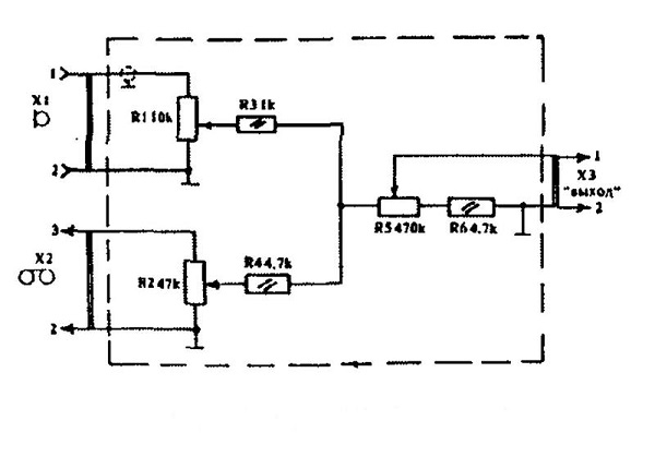
The summed signal coming from both sources is removed using a resistor R5, after which it goes to the output (X3) to the recording or playback device.
For the operation of this scheme no power required. To achieve a minimum level of noise, all elements must be well shielded. Due to the slight interference that may occur between channels, the signal-to-noise ratio is acceptable. The contacts of variable resistors R1 and R2, which are movable, are combined through 2 resistors - R3 and R4. This reduces their influence on each other during mixing.
Attention is drawn to the fact that the resistors (variables) R5, R1 and R2 have metal housings, and they must be connected both to each other and to the housing of the socket X1. In addition, they are connected to the common wire of the circuit, as well as to the body of the mixer.For this scheme it is recommended to use variable resistance type, not round, in which the regulator moves rectilinearly. This is done, to a greater extent, for convenience, to visually assess the position of the regulator, and thus determine the signal level.
Dual channel audio console
This mixer is two-channel and mono. The dual-channel remote can be used to sound various events, movies, as well as to mix the signal emanating from various kinds of musical instruments.
The design of the sound console used one chip, consisting of two amplifiers. One amplifies the signal from the microphone, and the other works in the adder circuit. To adjust the incoming signals in the apparatus, potentiometers are used, indicated in the diagram P1, P2, P3.

The output signal is adjusted by potentiometer P4. In case you want to bring a stereo signal to the input of the device, then the signals coming from the two channels (left and right) must be combined with the input of the mixer. This can be done with external resistors (10 kΩ).
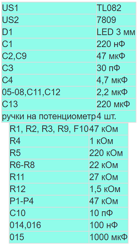
To power the device, you can use any source at 12V.It is important that the AN7809 chip be installed on the radiator.
A list of all radio components and their ratings are given in the table below.
How to make a circuit board
The easiest way to make a PCB is to use an iron and an image printed on a laser printer. If you are not the owner of lazernik, the image can be printed in any salon where printing services are provided.
It is important that the image be applied to paper with toner - powder, used only in laser printers and copiers.
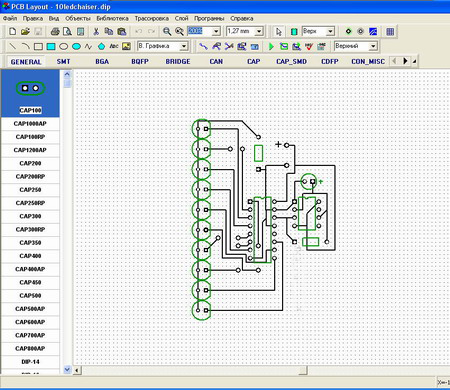
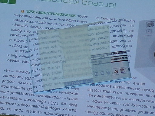
Also required purchase textolitebetter single-layer. It is sold on the radio market or in a specialty store selling radio components. But, to begin with, the PCB needs to be designed. For this purpose, different software is used, which can calculate and draw board tracks in automatic or manual modes. It is recommended to use DipTrace programwhich needs to be downloaded from the Internet. With this program it is possible to create, in addition to printed circuit boards, schematic diagrams. The program window looks like the figure below. On it you can see the finished layout of the future PCB.
Next, you need to do the following.
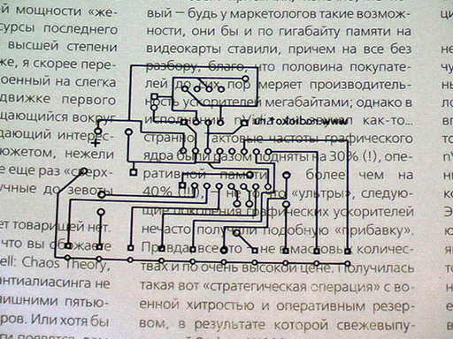
- Print the drawing you created using lazernik. Please note that the paper used for printing should be glossy, such as in glossy magazines. Just rip out the page and print directly on the text or image. It is recommended to make several copies just in case.
- Take a sheet of PCB and cut with a cutter (which can be made from a hacksaw blade) of a suitable size rectangle.
- Next, you need to prepare acetone, cotton discs and fine sandpaper.
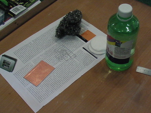
- Sandpaper a piece of the billet from the side where there is a foil, to the state that the matte layer is completely removed, and the foil becomes shiny.
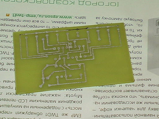
- Next, dip a cotton pad in acetone and carefully wipe the foil. The result should be as in the photo below.
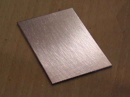
After degreasing the foil surface, it is very important not to touch it with your fingers. Otherwise, you will have to degrease the foil again. You can take only the edges of the workpiece.
In the next step, you will need to connect the blank and printed on paper scheme.
- Cut a piece of paper with a printed drawing in such a way that there is a margin for wrapping around it.
- Overlay the image of the drawing on the workpiece (picture on the foil) and wrap the excess paper, which can be secured with masking tape. As a result, you will receive an envelope, as in the figure below.
- Take the iron (make and model does not matter) and set the maximum heat on the thermostat.
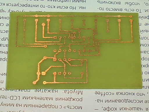
- Put the heated iron on the envelope, of course, on the side where there is no adhesive tape. Begin lightly stroking the paper. Press on the iron should be with a moderate effort, otherwise the toner will spread and smear on the workpiece. If you press lightly, then the toner badly clings to the foil layer of the workpiece. Warming up should be done evenly over the entire area of the workpiece. Especially it is necessary to warm up the edges, where the risk of toner peeling is increased, due to insufficient heating. The fact that the heating can be stopped is evidenced by the yellowing of the paper, as well as the bleed-out of the outline of the pattern on it.
- Turn off the iron and allow the envelope to cool for about 10 minutes.
- Take a suitable container and pour hot water into it. The temperature of the liquid can be determined by hand: if the water is so hot that you cannot hold your hand in it for a long time, then the temperature is suitable.
- Lower the envelope with the blank into the liquid for about 15-20 minutes. If you have hot water flowing from the tap, then you can not turn it off.
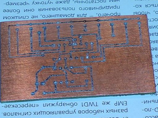
- After soaking it is necessary, by applying maximum accuracy, to separate the paper from the foil. Sticking pieces of paper should not be scraped. They need to gently roll with your fingers.
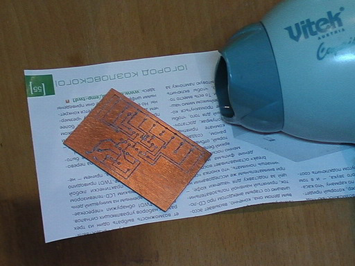
- Take a hairdryer and dry the billet well.
- In the next step, it is necessary to remove areas of the foil without a pattern, i.e. picker board. For these purposes it is customary to use ferric chloride. It is sold in banks, looks like rusty gruel, has an unpleasant smell and is diluted with thorough mixing with warm water. The solution is made at the rate of 100 g of water + 100 g of gruel. Liquids can be added less, as long as the solution completely covers the preform.
- Immerse the workpiece in the prepared solution. On average, etching lasts about 20 minutes. At the time of etching affects the concentration of the solution, as well as the size of the submerged part. In this case, it is very important to stir the solution with a glass or plastic stick or to rock the bath. If possible, put the container in warm water and change it as it cools so that the solution does not become cold.If after a specified period of time you notice an insufficient pickle, then it is necessary to increase the concentration of the solution by adding some ferric chloride to it.
- After a successful pickling remove the board from the solution, rinse it under running water and dry.
- Dampen a cotton pad with acetone and remove any remaining toner from the board.
- Now the toner-cleaned board with tracks must be drilled so that the legs of the radio components can be inserted into these holes. For holes you can use a drill with a diameter of 0.9 mm. Of course, the diameters of the conclusions must be set at the design stage, so that later not to redo the work.
- The final stage will be tinkering tracks. This is done using a liquid flux (30% alcohol solution of rosin). Heat the soldering iron and, picking up a minimum of solder on the sting, walk them along all the tracks. It should work out like in the following photo.
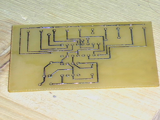
In this manufacture of printed circuit boards can be considered complete.
How to make a case for the mixer
The case for the sound console can be made by hand from any material that can be easily processed: plastic, plastic, plexiglass, PCB, etc.
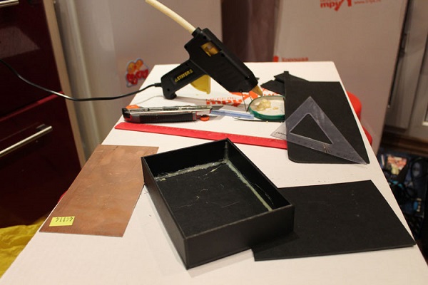
All parts are cut according to the size of the printed circuit board and the location of regulators, sockets that will go outside. The walls of the box is convenient to connect with a glue gun. Next, do the following.
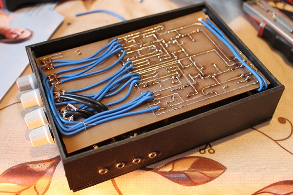
- It is necessary to put the board in the box and mark the places of drilling under the regulators and the sockets, then drill them.
- Insert the sockets into place and solder the wires from the board to them.
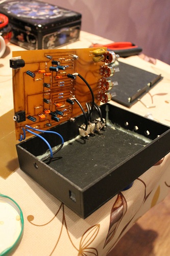
- Insert the card into the case.
- Glue the pieces of plastic to the bottom cover (bottom) so that you can screw the screws into them during assembly.
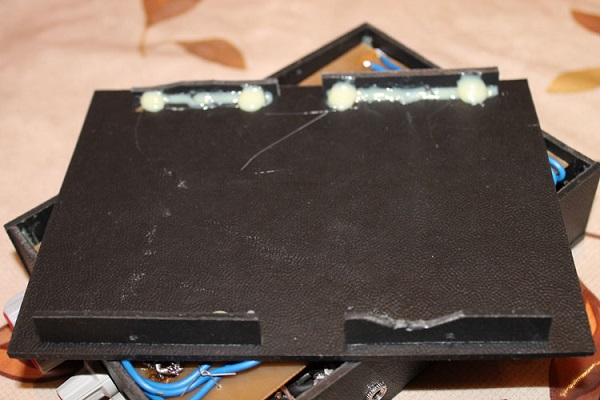
- Put the bottom in place and twist the screws into the appropriate places, pre-drilling holes a little smaller in diameter than the screw. If this is not done, the inserts will break or crack.
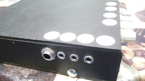
If your mixer circuit involves the installation of linear regulators and the same indicators, the grooves are cut on the top cover of the box.
This is where the mixer case ends.
/rating_on.png)