Disassembly and repair punch do it yourself
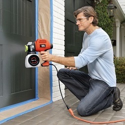
The perforator, like any electric tool, requires careful attitude, proper operation and timely preventive maintenance. If we neglect these norms, the apparatus can fail without having developed its own resource. Repair of the puncher with some faults can be done by hand, and to repair damage associated with the electric part of the engine, specialist assistance will be required.
Content
The main malfunctions of the punch and their external signs
All malfunctions of the unit can be divided into 2 groups: mechanical and electrical.

Mechanical damage
If a mechanical malfunction appears in the punch, its presence can identify by ear (noise rises, rattles appear).
You can also sense increased vibration or an unpleasant smell emanating from the body of the unit.
So, to mechanical damage include the following:
- failure of the device mode switch;
- worn gum drummer and striker;
- failure of the percussion mechanism;
- failure of the barrel of the unit due to wear;
- gear teeth breakage;
- breakage of the chuck, causing the drill to fly out.
Electrical faults
Malfunctions associated with the electrical part of the perforator may also be accompanied by an unpleasant smell from the body of the apparatus, sparking. You may also notice that the engine heats up quickly and buzzeswithout spinning, or smoke comes out of it.
Electrical breakdowns of the device include:
- the device does not turn on;
- breakdown of the start button;
- brush wear;
- collector clogging;
- violation of electrical contacts;
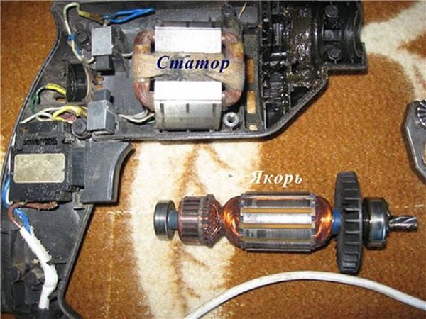
- burnout of the stator or rotor of the electric motor.
Punch disassembly algorithm
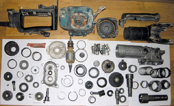
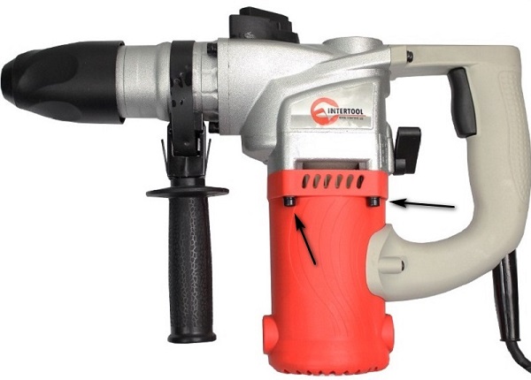
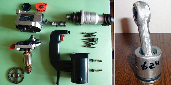
To eliminate mechanical and electrical faults (with the exception of breakage of the electrical plug) without disassembling the housing of the unit is indispensable. The most popular among masters, both domestic and professional, are the brands of drills Bosch, Makita, Interskol, Energomash. The design of units from different manufacturers is about the same, so the methods of disassembling the devices will be similar. But do not disassemble the device completely, since it will be difficult to assemble it back. The photo below shows what a completely disassembled punch looks like.
Disassembly of the cartridge
Disassembly of the unit for troubleshooting should be carried out carefully, with an inspection of each removed part. To the assembly did not cause difficulties, the disassembly process is better to photograph. If you do not find external defects on the device, it is recommended to start disassembling it from the cartridge.
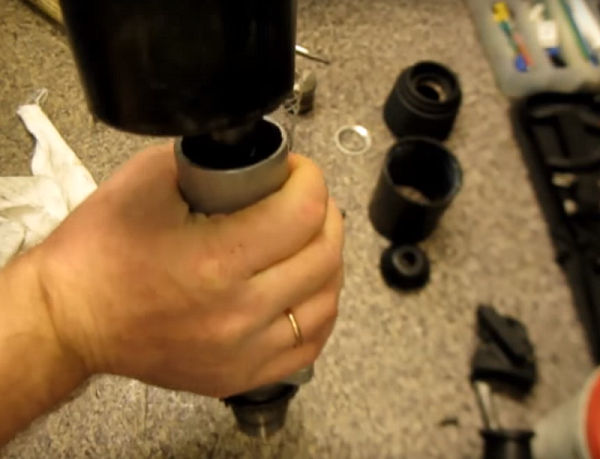
- First remove the boot (1), made of rubber.
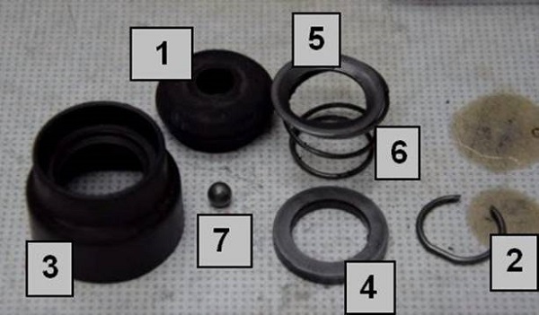
- Carefully, so as not to lose, use a screwdriver to remove the snap ring (2) and then the plastic boot (3).
- In the next stage, it is important not to lose small ballwhich is under the puck (4). Remove the washer (4), plate (5) and spring (6), as well as the ball (7). It is during the wear of these parts of the drill falls out of the cartridge. In some models of cartridges there may be additional balls and washers.
We disassemble the body
If disassembly of the unit housing is required, you must first remove the mode selector switch.
- Put a switch in position “Blow”. Usually in this place on the body is painted a hammer. In the case when this mode is not available, put the switch in the “Impact + drilling” position.
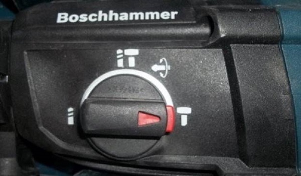
- Next, you should click on the button located on the switch knob and rotate it slightly below the icon with the image of a hammer to a characteristic click.
- After that, it is necessary to pry the switch with a screwdriver and, pulling it towards you, remove it. In some models of units, this switch can be screwed to the body with screws.
Disassembly of the electrical part of the punch
To get to the electrical part of the device, if you suspect that there may be a breakdown here, you must perform the following steps.
- Unscrew the screws holding the back cover and remove it.
- Unscrew the fastener holding the network cable.
- Next, pull the wires out of the fixings and remove the start button.
- Remove all wires attached to the stator.
- Remove the brushes by unscrewing the fixing bolts.
- Separate the electrical and mechanical parts of the apparatus by unscrewing the corresponding screws. For separation use “flat ”screwdriver.
- Remove the rotor from the gearbox. If you need to replace the bearings, use a special puller.
- Remove the air intake located in the body of the electric part of the grinder.
- Disconnect the stator from the case. In order to make it easier to get out of the casing, it is recommended to pull the stator with a light tap on the body with a wooden object.
If it is required to disassemble the barrel perforator, with the vertical arrangement of the electric drive, then first the handle is removed and then the bolts securing the engine are removed.
Replacing the motor brushes
The main sign that it is time to change the brushes is the formation of increased sparking in the area of the electric motor collector, rapid heating of the brush holders, as well as the smell of burning. When the brushes are not worn, the spark can only be seen under them. Otherwise, the spark can be seen around the whole circle of the collector.
The presence of a spark around the collector when the brushes are not worn is a sign of bearing wear, a broken rotor or stator insulation, burned collector plates, a stator or rotor burned out.
Another sign that a stator has burned out is the presence of sparks just under one electrode. If you have a tester, then they can check stator and rotor: measure alternately the resistance on the rotor and stator. If it is the same on both windings, then with the stator everything is in order. If you notice obvious signs of problems with the rotor or stator in your grinder, you will have to carry the device to a service center for repair. As for the brushes, they can be changed independently.
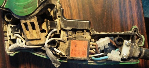
To get to the place where the brushes are installed, you will need to disassemble the case in which the engine is installed, or simply remove the back cover. Opening the lid, you will see the brushes, fixed in special holders. The photo below shows how these parts look.

Brushes that are installed on the engines of perforators, there are 3 types.
- Graphite - they are distinguished by durability, but since they are very hard, they are not ideally lapped to the collector, which negatively affects the latter.
- Coal - easy to grind in to the collector, providing good contact, but wear out quickly.
- Carbon-graphite –Ideal option, as they are a mixture of 2 components that complement each other.
It is very important not to wait for the engine to spark, and after that change the brushes. Replacement is needed after their wear at 1/3 of the nominal value (8 mm). Even if one brush has worn less than the other, you still need to change both.
Pay attention to the condition of the spring in the new brushes and fixing the contact. If the spring will fly off while the engine is running, it will receive significant damage. Also, if the spring is weak, it cannot provide good contact.
Be sure to before you change the brush, you need a good clean rotor and stator from residues of graphite or coal dust. These parts can be cleaned with technical or medical alcohol.
Next, you should fix the electrodes in the holders and grind them to the collector.To do this, put a piece of sandpaper of fine grain on the collector and produce rotational movements in different directions. grinding electrode. Grinding in continues until the contact area of the electrode is round. This will provide the best fit to the collector plates and, accordingly, the best contact.
Diagram of the percussion mechanism, its malfunctions and repair
Percussion mechanisms of perforators differ in their design, depending on which family the apparatuses belong to. Therefore, the repair of these mechanisms will occur according to different principles.
Barrel drills
Perforators with a vertical engine are usually equipped with a percussion unit based on a crank mechanism. Below is a diagram of a percussion mechanism of this type.
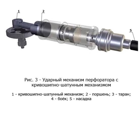
The following photo shows the apparatus in section, where you can see the location of the KSHM.

The shock mechanism of the unit with a vertical engine may have the following malfunctions. The connecting rod mechanism has a separate bearing, which is mounted on the cam of the eccentric wheel, but sometimes it can be located at the base of the connecting rod.In some models of rotary hammers, a sliding bearing (instead of a rolling bearing) may be installed at this place, requiring constant lubrication. If it is not there, or it is already old, then this node wears out. When repairing it is necessary to completely replace the connecting rod and eccentric keg.
Another common problem is warlock broke. This fault can be calculated if you notice that there is no more impact on your grinder. To get to the striker, you need a complete disassembly of the barrel device. It is done as follows.
- Disconnect the barrel from the punch body, remove the cartridge (see description above). Knock the barrel on the table so that a piston falls out of it. Take a rubber hammer and knock the barrel out of the body.
- Remove the bearing retaining ring.
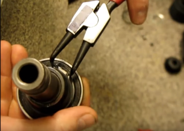
- Remove the bearing itself and gently tapping the table to remove the balls.
- After removing the 3 balls, you can pull out the raster sleeve.
- Also, as in the previous case, remove the balls on the hub, just do not confuse them with those that were removed earlier (these balls are of smaller diameter). After removing the balls, you need to insert a screwdriver into the sleeve and push out the head.
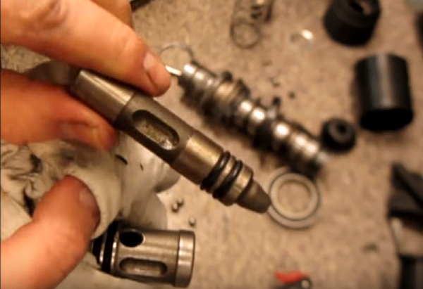
In this case, the whole warrior. But if it is broken, then replace it with a new one. You should also pay attention to the sealing gum and the seals in the body of the trunk. If they are worn out, they must be replaced.
Pistol-type drills
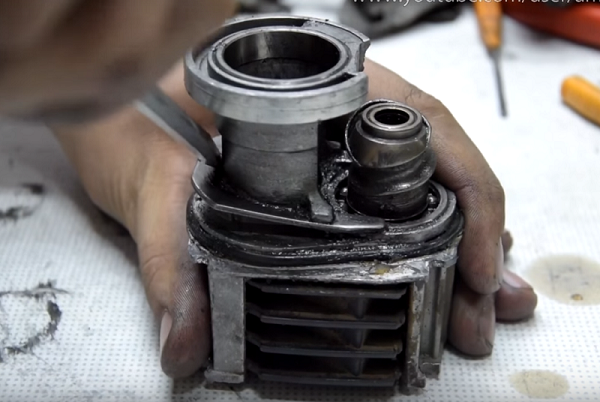
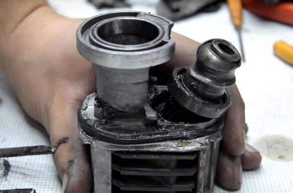
The device of the percussion mechanism of a pistol-type unit is slightly different from that of the same purpose mechanism installed in a barrel-type apparatus.
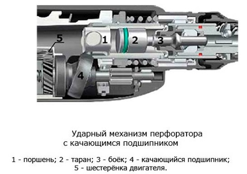
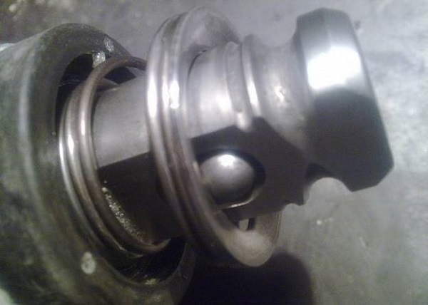
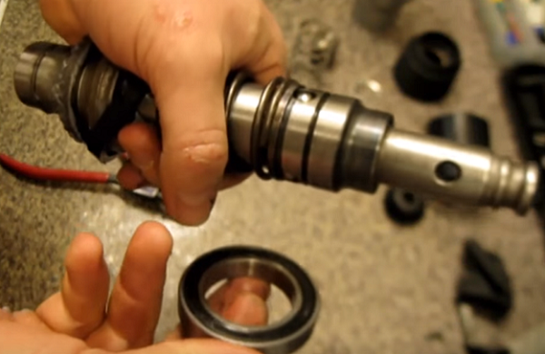
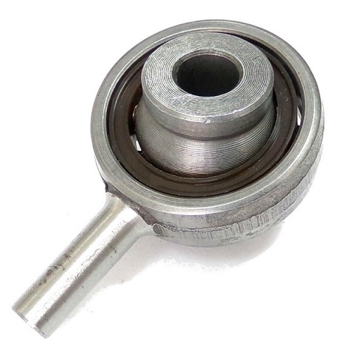
Its main difference is that the piston is set in motion not by means of a connecting rod, but by a rocking (“drunk”) bearing. Therefore, the most frequent failure of this unit is the wear of the “drunk” bearing that needs to be replaced.
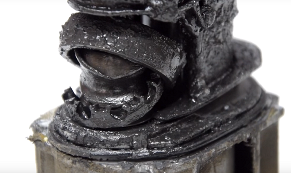
The following photo shows the destroyed “drunk” bearing, which is the reason that the hammer drill stopped hammering.
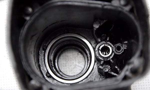
The oscillating bearing is removed using a flat screwdriver, which you need to pick up the bracket, and remove it. After that, the bearing is easily separated from the gearbox housing.
When replacing a collapsed bearing should be good wash gearbox, since it is in his case that fragments of a broken part may remain.
After cleaning and installing a new bearing, apply a greasy layer of grease to this unit.
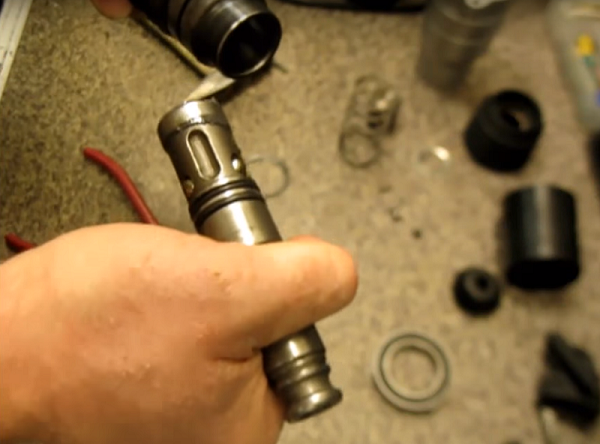
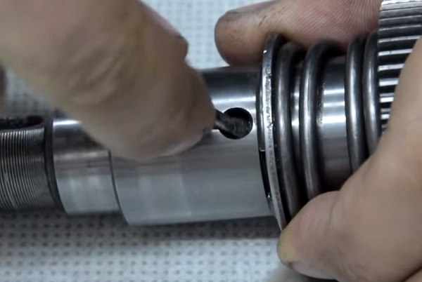
Also, the reason that the device does not hit, can serve as a broken firing pin. To get it, you need to remove the retaining ring, which is visible in the hole.
Take a small screwdriver, pick up the ring with it, and slide it to the right (towards the gear).
Do the same on the other side of the part. Next, insert a screwdriver into the hole in the part and push the removed internal parts of the mechanism.
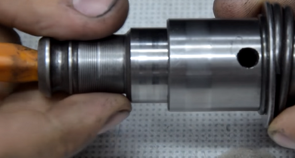
After this action, it is easy to get the retaining ring, and the body, which contains the broken strike head.
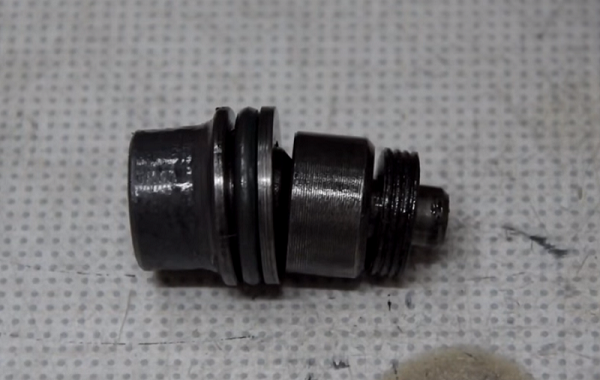
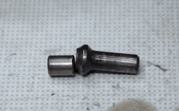
If you disassemble this case, then you will see the "culprit" of the malfunction, due to which the Bulgarian does not hammer.
When assembling a percussion mechanism, do not forget to apply grease abundantly on all its parts.
Other mechanical failures and their elimination
In addition to breakdowns associated with a percussion mechanism, other mechanical breakdowns can occur in the perforator.
Mode switch
There are cases when the mode switch of the unit fails. This is mainly due to dust clogging this node. To fix the switch, you will need to disconnect it from the case (see above for how to do it) and clean it from dirt.If you find any damage to the plastic parts of the switch, you will have to replace it.
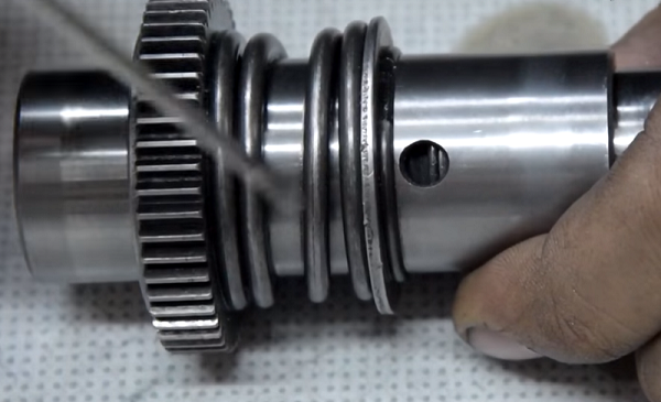
Gears with oblique tooth
The reason that the device stopped working normally, namely, it stopped drilling and hammering, can be covered in worn teeth on the rotor shaft.
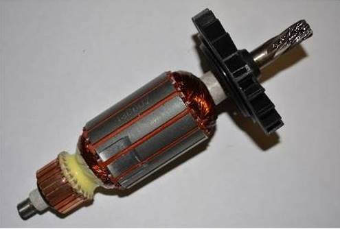
If this happens, the teeth will be worn and at the intermediate helical gear.
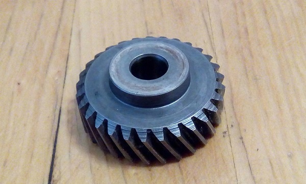
This problem occurs when a tool is jammed or a clutch is malfunctioning. Breakage is eliminated by replacing the intermediate gear and the rotor of the engine.
The drill does not hold in the cartridge
The reason that the perforator does not hold the drill, lies in the failure of the cartridge and the wear of its parts:
- ball deformation has occurred;
- worn restrictive ring;
- gave a drawdown spring.
You will need to disassemble the cartridge and replace the problem parts.
Boer stuck in the punch
The reasons for the fact that the drill is stuck in the apparatus cartridge may be the following.
- Before installing the tooling, you did not apply lubricant to its shank. It will be necessary to move the cartridge sealing gum and inject the WD-40 tool into the landing area.
- Dust fell under the balls. Perform the same operation as in the paragraph above.
- If you used a conventional drill inserted in an adapter in the punch, also process it liquid WD-40, wait a couple of minutes, and, lightly tapping with a hammer on the surface of the clamp, loosen the tooling in different directions. Usually, after these actions, the clamping jaws open and allow you to remove the drill bit.
- The shank of the tool has riveted. You will need to first pour the WD-40 fluid and try to pull out the drill. If nothing happens, then you need to disassemble the cartridge and knock out a snap. You can also use tips on how to get a tool stuck in the machine, from this video.
/rating_off.png)