Self-made adapters for a milling cutter
The use of various devices for manual milling cutter significantly expands the capabilities of this unit, as well as increases comfort and safety when working with it. On sale there are ready-made models of devices intended for use in a pair with a router, but, as a rule, they are expensive. Therefore, many masters prefer to make fixtures for this unit with their own hands.
Content
Table for hand mill
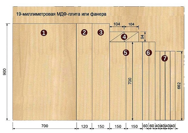
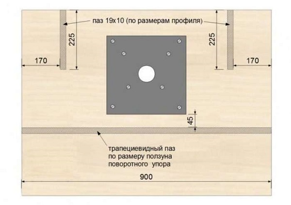
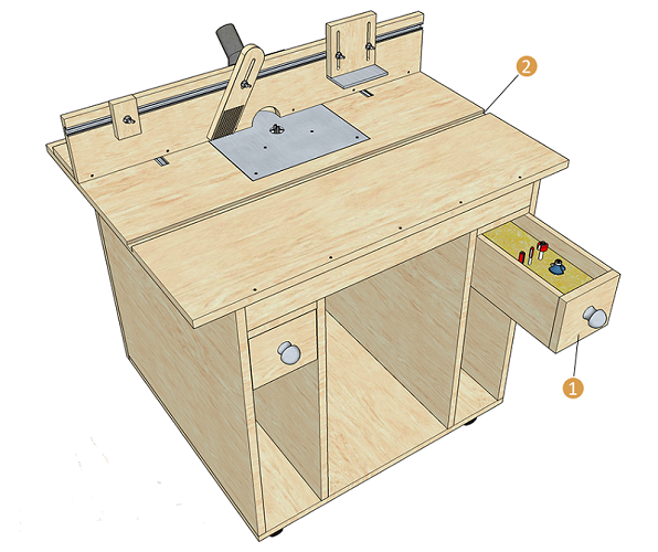
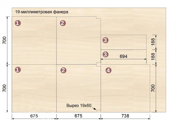
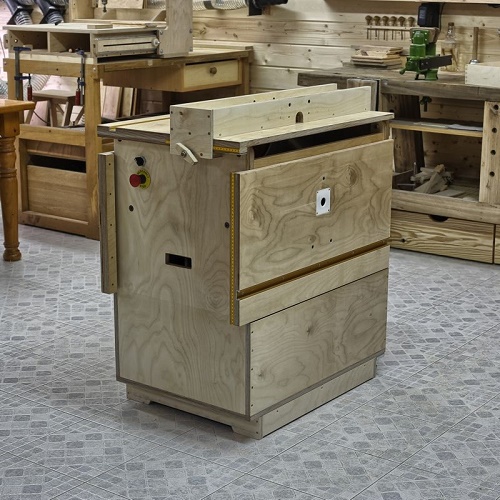
If you fix the manual milling machine in a special way under the table, you get a universal carpenter machine that allows you to produce accurate and fast processing of long and short pieces of wood. To make a table for a router, first you need to prepare the necessary parts for the assembly of the whole structure. The figure below shows a cutting chart on which all the details of the future milling table are located. They are cut with a circular or format-cutting machine.
![]()
The device can be made plywood, chipboard or MDF. The nesting map shows a material thickness of 19 mm, but this is not a prerequisite. The table can also be assembled from 16 or 18 mm thick plates. Of course, for the manufacture of tabletops it is better to use laminated or plastic-coated sheet materials, which will allow the workpiece to easily slide on the surface.
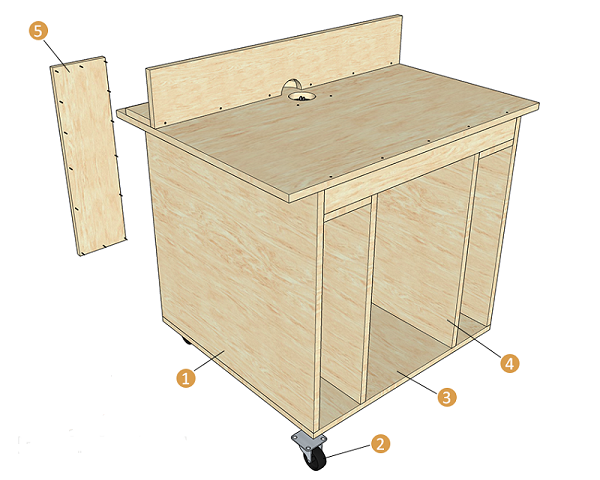
Also note that this homemade table is designed for installation on goats. If you need a tabletop option, the tsargs (5) should be made much wider than 150 mm. Their width should be slightly larger than the height of the apparatus so that it can be placed under the table top.
If the details of the table will be cut out of plywood or MDF, then their ends should be polished. The ends of parts made of laminated chipboard will need to be covered with a melamine edge using an ordinary iron.
Worktop making
Installation of the router in the table can be done both with the use of the mounting strip and without it. Worktop preparation for direct attachment to her the unit is as follows.
- Since the main plate has a length of 900 mm, its center will be 450 mm from the edge. Put a dot in this place and use the square to draw a line.
- Remove the plastic overlay from the sole of the device.
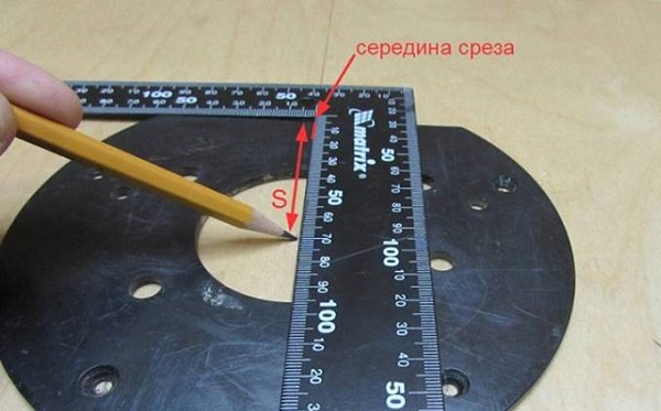
- Find the middle of the cut on the lining and draw a line through the center of the sole using the square.
- Position the pad on the center line of the main plate so that the center of the sole coincides with it, and mark the center of the future hole in the worktop with a pencil.
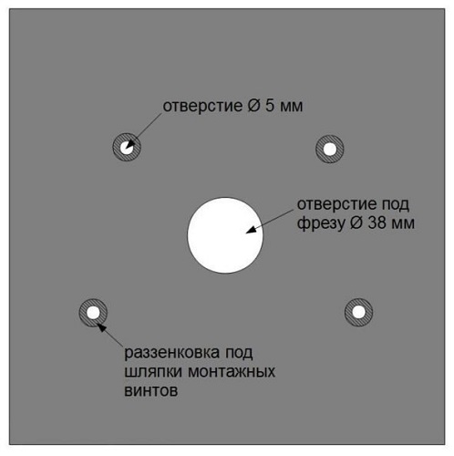
- Next, you should make a markup for the mounting screws.
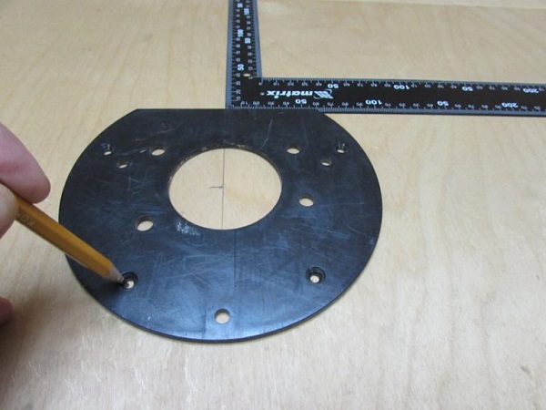
- Drill holes through which the unit will be attached to the table. Be sure to rezenkuyte them, so that the caps of the screws were slightly recessed into the tabletop.
- Drill a central hole with a diameter of 38 mm.
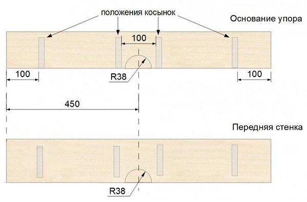
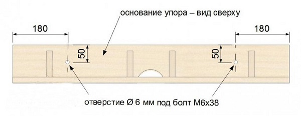
- The next step is to make a parallel emphasis. Using an electric jigsaw or router, make semicircular cuts on the front wall of the support, as well as on its base.
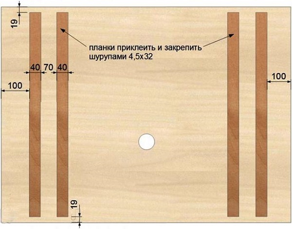
- Screw the kerchiefs to the stops.Below is a drawing that shows all the indents for placing the gussets.
- Screw the connecting strips to the bottom of the tabletop.
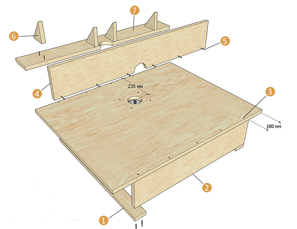
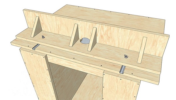
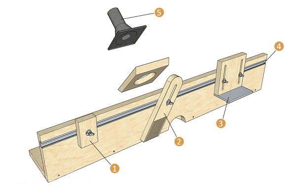
- Assemble the milling machine using the diagram below.

Mounting the unit using the mounting plate
When installing the device on the main plate, its thickness significantly reduces the reach of the cutter. Therefore, to install the unit on thick tabletops, it is customary to use thinner mounting plates made of durable materials (steel, aluminum, polycarbonate, getinax or fiberglass). The plate is made as follows.
- From a sheet, for example, PCB, cut a square billet 300 x 300 mm.
- From the top of the plate, attach the plastic cover removed from the bottom of the router.
- Pick a drill bit that matches the diameter of the mounting screws and drill the holes in the plate using the plastic cover as a template.
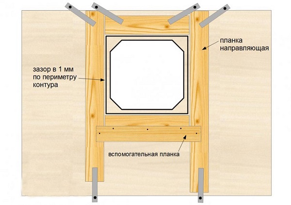
- Place the plate on the countertop and circle it with a pencil. After that, inside the resulting contour, draw a square with cut corners, as shown in the following figure.
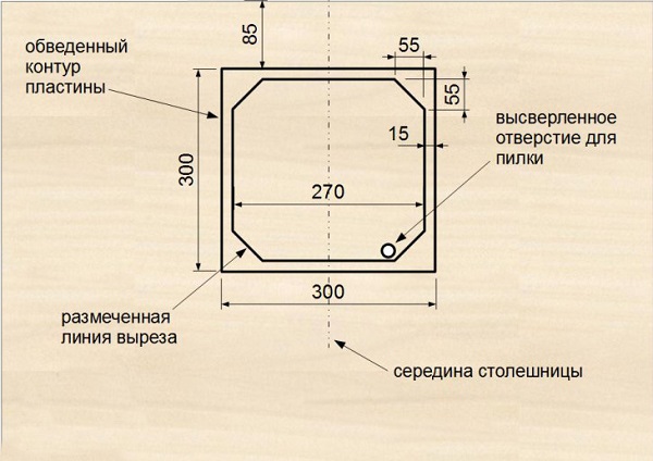
- This figure with beveled corners must be cut out with a jigsaw, having previously drilled a hole in it to enter the saw.
- After cutting the inner part around the outer contour, fasten the strips using clamps. They will serve mold cutter template. The thickness of the slats should be sufficient so that when setting the machining depth, the thrust bearing of the milling cutter is in the area of the edge of the guides.
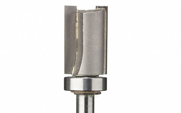
- For milling grooves, fasten a rolling cutter with upper bearing in the collet of the machine.
- Set the depth of processing. It should be equal to the thickness of the plate intended for mounting the unit.
- Mill this section of the tabletop in a set pattern in several passes.
- Place the plate in the groove. It should be flush with the surface of the main plate. If the plate protrudes slightly, then add a little more dive depth using the micrometer screw and re-pass the cutter.
- Mark and drill holes in the sampling angles for fixing the plate.
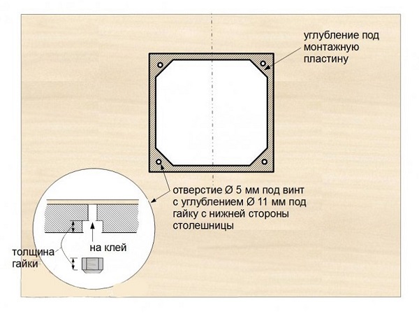
- Place the mounting plate in the prepared seat and, holding it, turn the tabletop. After that, drill holes in the plate for fasteners. To hide the caps of the bolts, pry through the holes on the front side of the lining.
- Also, all the holes on the back side of the tabletop, designed to secure the plate, should be expanded to fit self-locking nuts with a drill with a diameter of 11 mm. Nuts need to be put in the holes on the epoxy glue (for alignment, you can tighten the bolts in them).
Stop improvement
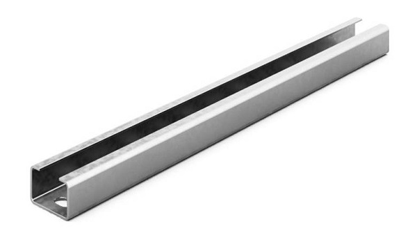
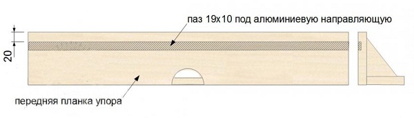
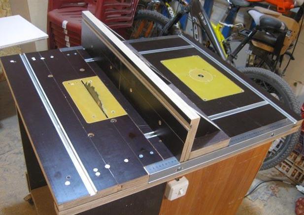
The parallel stop can be modified to make the setting of the milling table more convenient and quick: for this you need to cut C-shaped guides into the tabletop. The profile may be aluminum. For insertion, a straight groove cutter is used. The profile fits into the prepared groove and is fastened with screws.
Next, you should pick up the hex bolts of such a size so that it can enter into the C-shaped profile and not turn in it. Drill 2 holes in the base of the parallel stop corresponding to the bolt diameter.
You should also embed the C-shaped profile into the front plate of the support to secure various clamps and protective covers on it.
The support is fastened to the table top with the help of wing nuts.
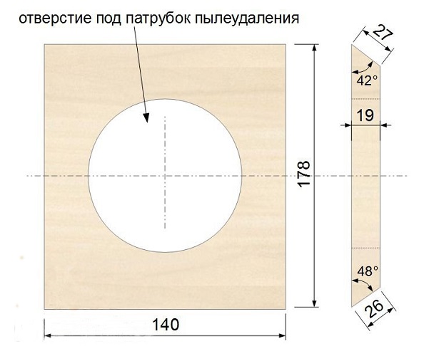
On the back side of the support can be done camera for connecting a vacuum cleaner. To do this, it is enough to cut a square out of plywood, drill a hole in it for the vacuum cleaner nozzle and fasten the resulting cover to the kerchiefs.
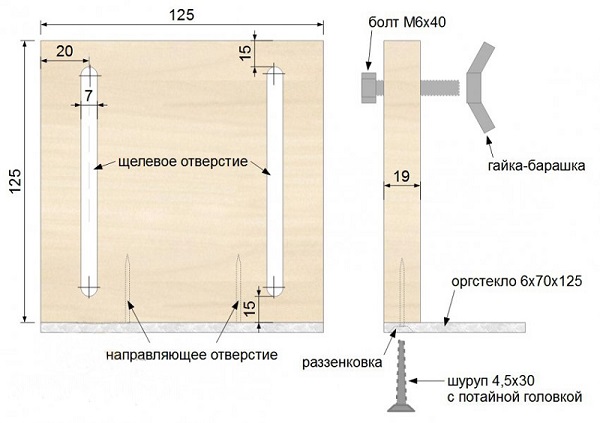
Also you can add to the stop safety shieldmade of MDF or laminated chipboard and a small rectangle of Plexiglas. For sampling grooves, you can use a jigsaw or a milling cutter with a slotted cutter.
To be able to handle small parts, it is necessary to make the clamps and clamps of plywood or MDF.
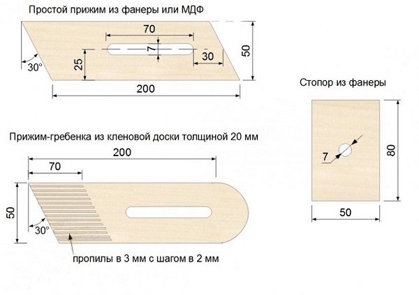
Clamp-comb it is made on a circular saw with a step between saw notches of 2 mm.
![]()
If desired, you can make a milling table with tool boxes.
![]()
Making the base table
If it is required to make a stationary machine from a manual mill, then one cannot do without making a solid base. Below is a map of the cutting with the details on it that will be required to assemble the table base. The dimensions of the parts will need to be corrected if sheet material of a different thickness is used.
![]()
All the details of the table for the hand mill are collected with the help of confirmats. For the convenience of moving the table to its bottom, you can attach rollers.If you expand this table a little and attach a circular saw in its free part, you will get universal table for a milling cutter and circulars.
That the machine occupied less places, it can be made by the principle of a table book with the table-tops descending from both parties.
Homemade accessories for the router
To expand the functionality of this unit on sale are quite expensive devices. But in order to save money, the owners of milling cutters try to make various adaptations with their own hands, which work no worse than the factory ones.
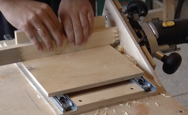
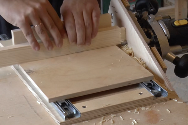
Tender Cutter
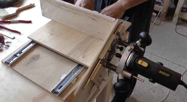
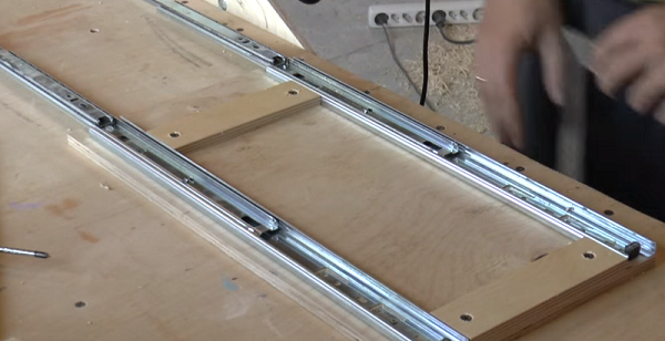
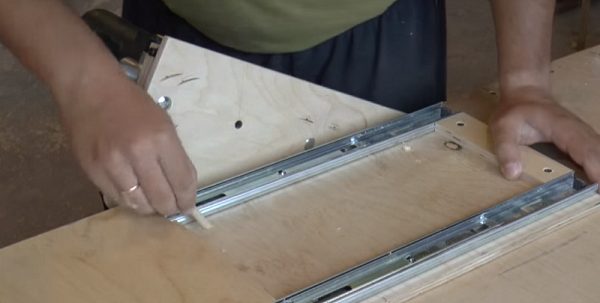
A simple shiporezka for a milling cutter is made of two pieces of plywood and a pair of telescopic furniture guides. The milling cutter is installed on the platform with a hole for the tool. The platform is attached to the workbench at an angle (for more convenient positioning of equipment in height), as shown in the photo below.
So, tenon fixture is made in the following order.
- Cut 2 pads of the same size out of plywood. Size can be any.
- Place two telescopic rails parallel to each other along the edges of the first platform and screw themscrews.
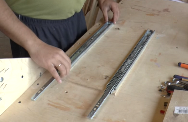
- For more accurate positioning of the guides, you can fasten two bars of the same length along them.
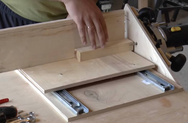
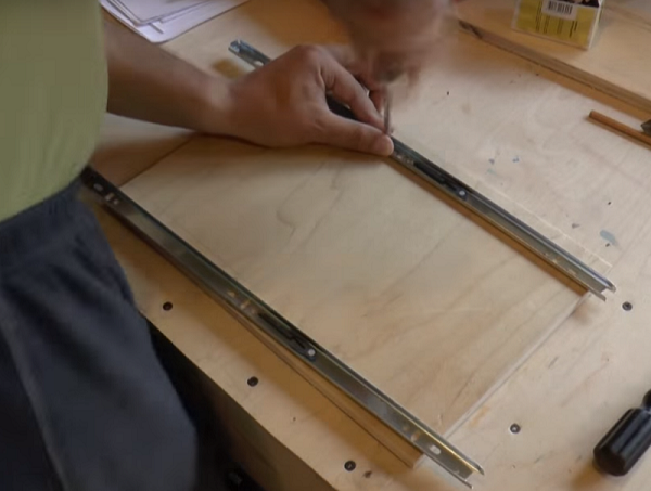
- It is necessary to put forward reciprocal strips and put a second platform under them flush with the first. Put a pencil on the second platform point through the bar, and then draw a line through them.
- Remove the strips from the guides by clicking on the plastic “antennae” located on their reverse side.
- Lay the strips on the marking board so that the line passes through the center of the fastener holes, and fasten them with screws.
- Carefully align the 2 guides and push them in (you should hear a click). If you insert a part with a warp, you will break the telescopes, and the balls will fall out of them.
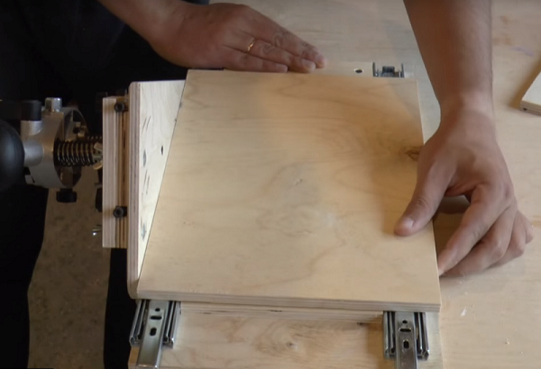
- Between the vertical stop with the unit and the movable table is necessary stand a certain distance. This is done so that when lowering the cutter it does not touch the table area. Since in this case the maximum reach of the cutter will be about 25 mm, it is possible to temporarily lay a bar of the same width, that is, 25 mm, between the table and the stop. The plank will allow to place the structure parallel to the vertical stop
 .
. - In the next step, holding the fix, drill 2 holes for the dowels. They will allow you to quickly position the shiporezka on the workbench. When the holes are ready, insert a pair of dowels into them. Now you can remove the bar between the stop and the fixture.
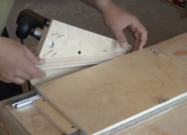
- Now, when the movable table is fixed, a vertical stop should be installed on its upper platform, as shown in the following figure. For rigidity, the support is supported by two kerchiefs.
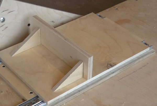
- When all the elements of tenoning will be fixed, you can proceed to the tests. Place the workpiece on the fixture table and press it against the stop. Set the required cutter height, turn on the unit and profile the workpiece.
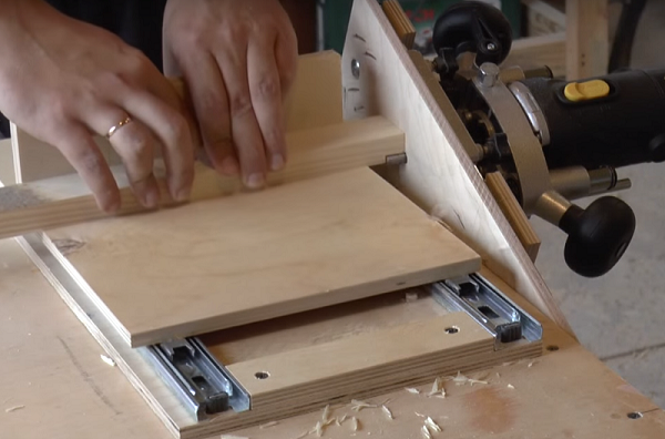
- After the first pass, turn the workpiece 180 degrees and repeat processing.
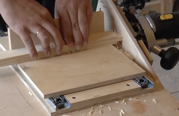
- Rotate the workpiece 90 degrees, placing it on the edge, and repeat the operation.
- Rotate the part 180 degrees and finalize the spike.
As a result, you get a smooth and high-quality spike.
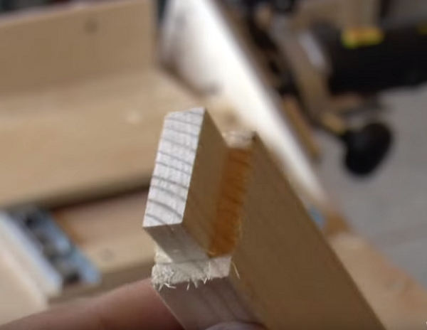
By varying the height of the cutter relative to the tenoning point, it is possible to produce spikes of various thickness.
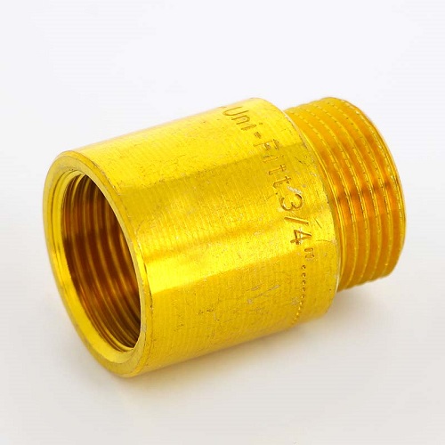
Copy sleeve
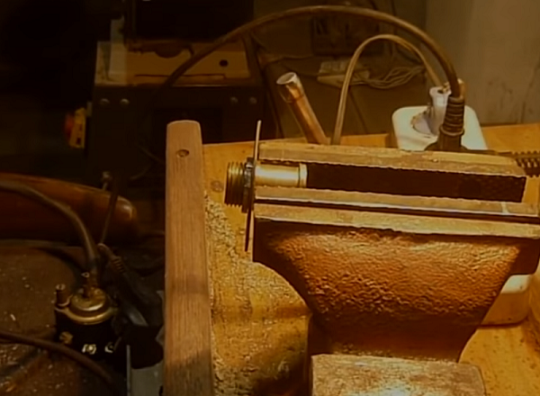
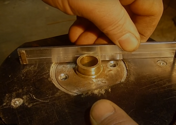
If there was no copy sleeve in the kit for your router, then it can be made in just 30 minutes from improvised means. For homemade need a metal or dural washer, which can be made of sheet metal, and a water threaded extension.
The copy sleeve is manufactured by the following method.
- Pick up a nut suitable under a carving of the extender and cut it by means of the Bulgarian so that the thin ring has turned out. After that align it on the grinding machine.
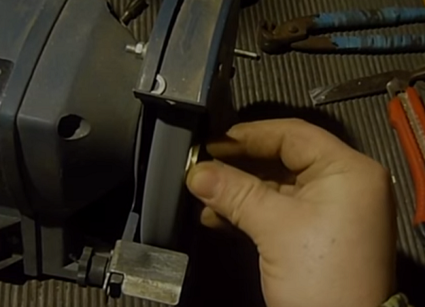
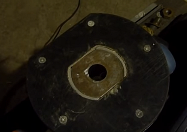
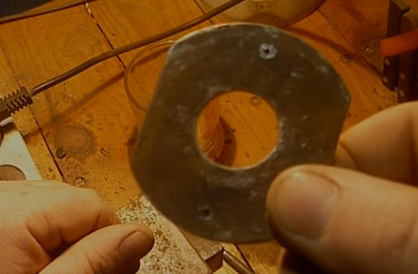
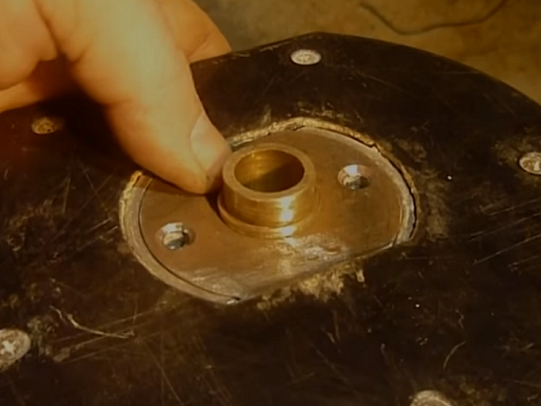
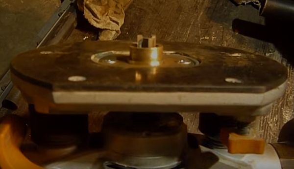
- It is necessary to make a round platform for the sleeve of sheet metal or aluminum with a thickness of 2 mm. Depending on the model of the unit, a hole in its sole may have different shape. In this case, the ground should have cuts on the sides that are ground on a grinding machine.
- With the puck on both sides, place it on the bottom of the unit.
- Place the unit, without removing the washer, vertically and mark with a pencil places for fasteners through the holes in the bottom of the apparatus.
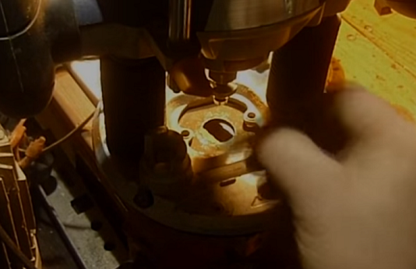
- Places marked with a pencil, you need to nakvernit for accurate positioning of the drill.
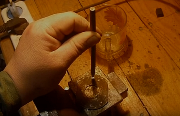
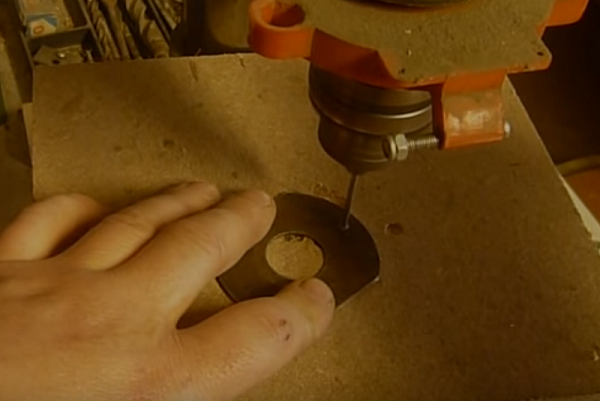
- First, drill holes with a thin drill, and then with a drill that matches the diameter of the mounting bolt.
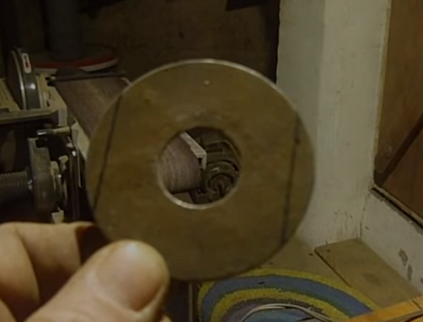
- Put the washer on the threaded extension and tighten the ring nut.Clamp the part in a vice and cut the excess thread flush with the nut using a grinder.
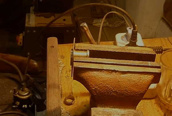
- Clamp the part in the vice with the other side and shorten it slightly.
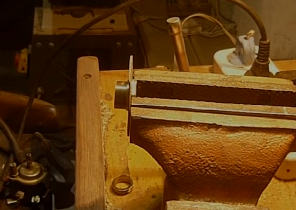
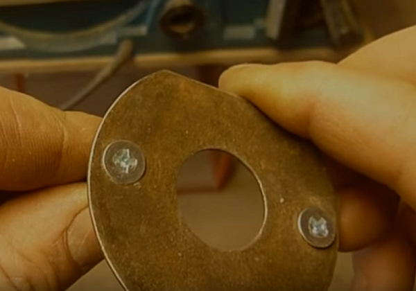
- Align the part on the grinding wheel, insert it into the bottom of the machine and fasten it with screws. The ring nut should be just below the bottom of the unit.
Guides for working with a router
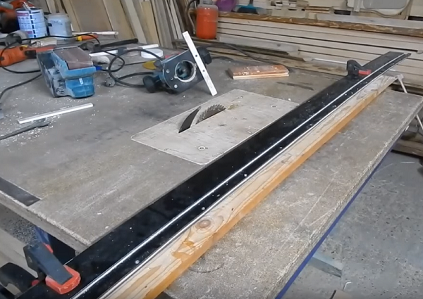
If you want to choose a very long groove in the workpiece, then you need a device for a router, which is called a tire. Finished metal tires can be bought in specialized stores. But they are also easy to make with your own hands from plastic, plywood or MDF.
The thickness of the material should be about 10 mm, so that parts can be pulled off with screws.
The guide for the unit is very simple.
- Cut into three circular strips. One wide, about 200 mm, and 2 narrow - 140 and 40 mm each.
- Also make a small plank of the same material, about 300 mm long and 20 mm wide.
- Place a 140 mm wide part on a wide strip, align it with the edge and twist both parts with screws.
- Lay on top of the wide strip, opposite the bolted part, a narrow strip 40 mm wide.For precise positioning, lay a 20 mm wide bar between the upper parts and screw the narrow strip with screws to the lower part. Thus, you get a long tire with a groove width of 20 mm.
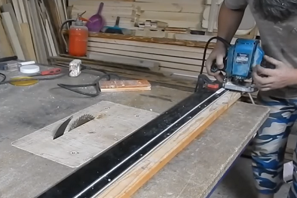
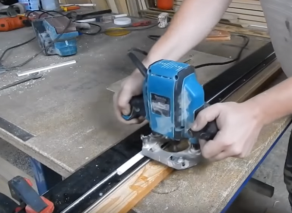
- Take a 20 mm wide bar and screw it to the bottom of the machine, as shown in the following photo. To select the groove is selected straight or shaped groove cutter and secured in the collet apparatus.
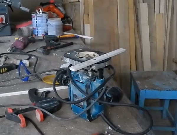
When all fixtures have been prepared, follow these steps. Put the workpiece on the workbench, which needs to be processed along its entire length, place the tire on it, securing it with clamps. Insert the bar attached to the bit of the router into the guide slot. Start the unit and profile the workpiece along the entire length.
If you want to choose a deep groove, the processing takes place in several passes, so that the tooling is submerged in the workpiece gradually.
/rating_on.png)
/rating_off.png)