Alteration of the welding inverter in a semiautomatic device
Automatic welding semiautomatic is a fairly popular device among professional and home craftsmen, especially those who are engaged in body repair. This unit can be purchased already in the finished version. But many owners of inverter welding machines are asking: is it possible to convert an inverter into a semiautomatic device, so as not to buy another welder? Making a semiautomatic device from an inverter with your own hands is quite a difficult task, but with a strong desire it is quite feasible.
Content
Required materials and tools
To assemble the unit you will need the following elements:
- inverter welding machine;
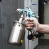
- a torch, as well as a special flexible hose, inside of which a gas pipeline passes, a guide for the wire,power cable and electric control cable;
- mechanism for uniform automatic wire feed;
- control module and motor speed controller (PWM controller);
- protective gas cylinder (carbon dioxide);
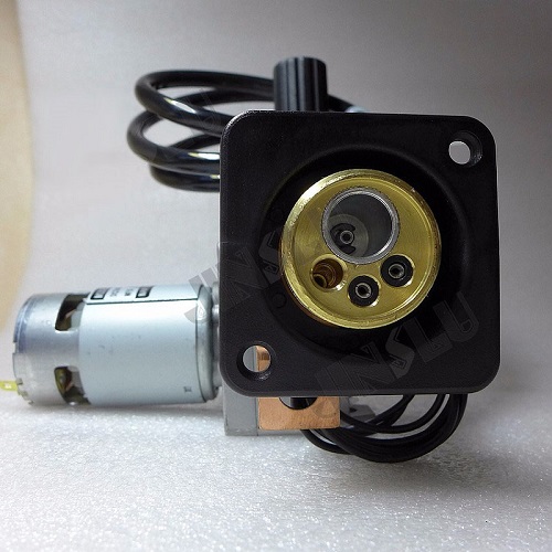
- solenoid valve for cutting off gas;
- coil with electrode wire.
In order to assemble a homemade semi-automatic machine from a welding inverter, the latter must produce a welding current of at least 150 A. But it will have to be slightly modernized, since the current-voltage characteristics of the inverter are not suitable for welding with an electrode wire in a protective gas environment.
But more about that later. First you need to make the mechanical part of the semiautomatic device, namely the wire feeder.
Electrode wire feeder
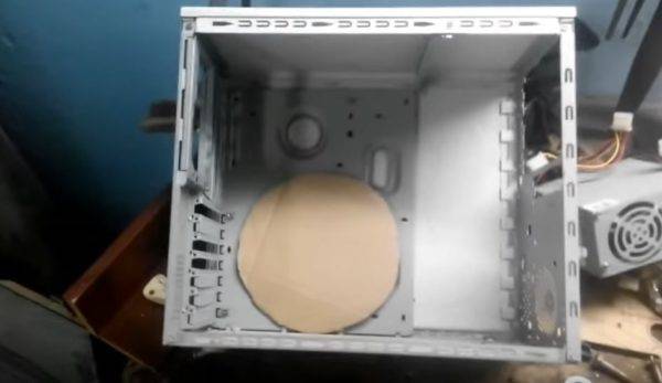
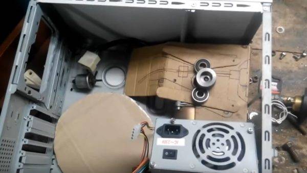
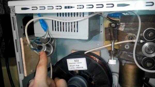
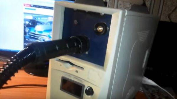
Since the feeder will be placed in a separate box, it is ideal for this purpose. computer system case. In addition, no need to throw away the power supply. It can be adapted to the operation of the pulling mechanism.
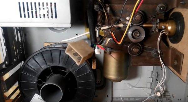
First, you need to measure the diameter of the coil with wire or, drawing it on paper, cut a circle and insert it into the body.Around the reel should be enough space to accommodate other nodes (power supply, hoses and wire pulling mechanism).
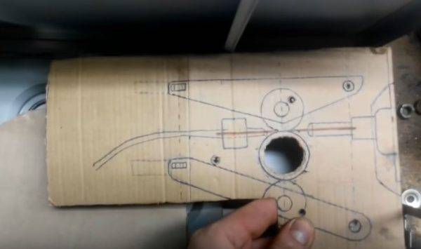
The wire drawing device is made of a car wiper mechanism. It is necessary to design a frame for it, which will also hold the pinch rollers. The layout must be drawn on thick paper in real scale.
The feeder must be installed in the housing so that the connector is located in a convenient place.
In order to feed the wire evenly, all components must be fastened exactly opposite each other. The rollers must be centered relative to the hole for the inlet fitting, which is located in the connector for connecting the hose.
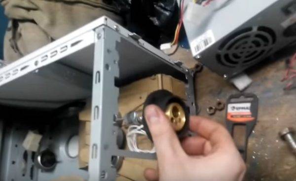
As roller guides you can use suitable diameter bearings. They use a lathe to grind a small groove through which the electrode wire will move.For the case of the mechanism, you can use plywood with a thickness of 6 mm, textolite or durable plastic sheet. All elements are fixed on the base, as shown in the following photo.
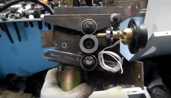
As the primary wire guide used axially drilled bolt. The result is a semblance of a wire extruder. At the entrance of the nozzle is put on a cambric, reinforced by a spring (for rigidity).
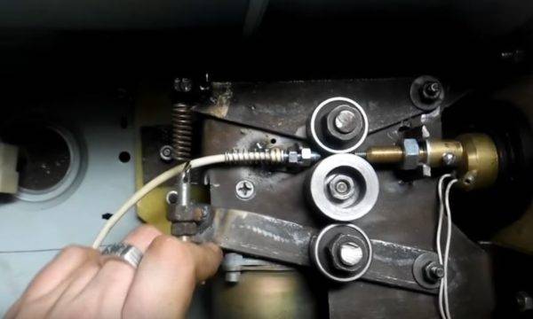
The rods on which the rollers are fixed are also spring loaded. The clamping force is set using the bolt located below, to which the spring is attached.
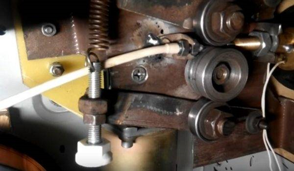
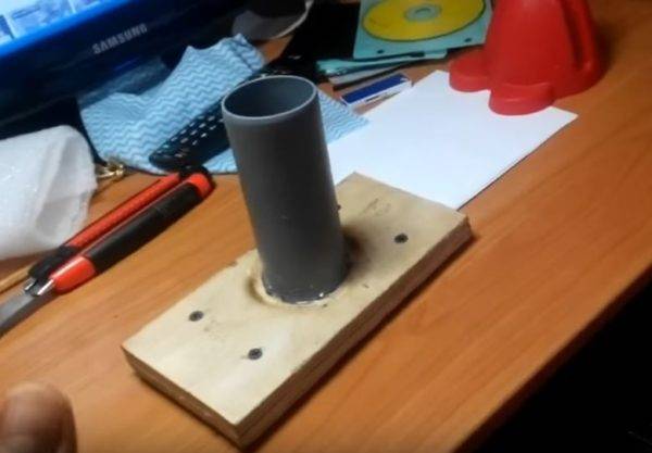
The basis for fixing the reel can be made from a small piece of plywood or PCB and trimming a plastic pipe of suitable diameter.
Further, all components must be carefully placed in the case.
Control circuit mechanics
In order to achieve a good weld quality during welding, it is necessary to ensure the wire feed at a certain and constant speed.As the engine from a screen wiper is responsible for the speed of the tooling, it is necessary to have a device that can change the rotation speed of its armature. A ready-made solution that can also be purchased in China is suitable for this, and it is called PWM controller.
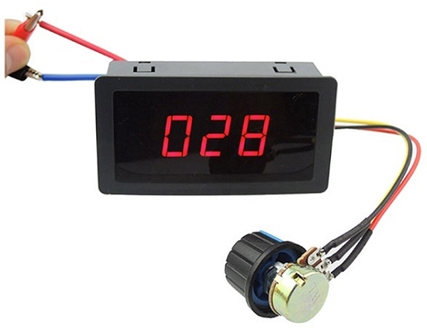
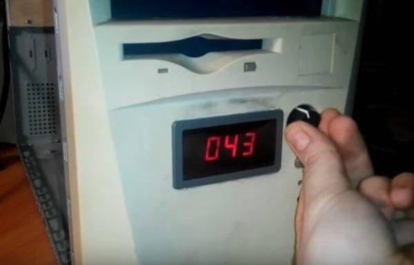
Below is a diagram from which it becomes clear how the rpm controller is connected to the engine. The controller controller with a digital display is displayed on the front panel of the case.
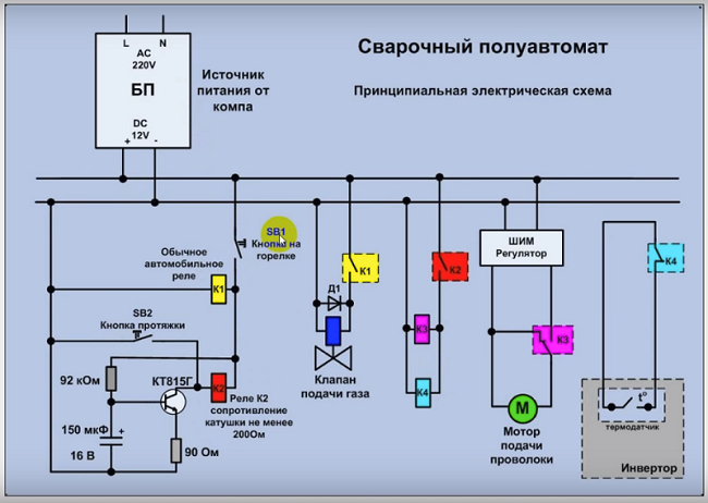
Next, you need to install gas valve relay. It will also control the engine start. All these elements must be activated when pressing the start button located on the handle of the burner. At the same time, the gas supply to the welding point must be ahead (about 2-3 seconds) of the beginning of the wire feed. Otherwise, the arc will ignite in the environment of atmospheric air, and not in the environment of protective gas, as a result of which the electrode wire will melt.
The delay relay for homemade semi-automatic can be assembled on the basis of the 815th transistor and capacitor. To get a pause of 2 seconds, a capacitor of 200-2500 uF will suffice.
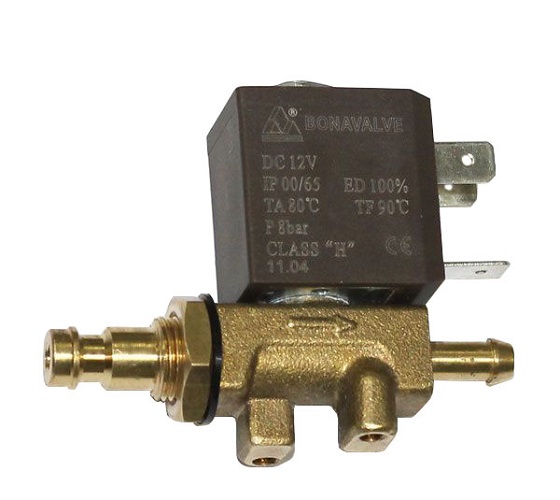
Electromagnetic shut-off valve placed in any place where it will not interfere with the operation of mobile nodes, and is connected to the circuit according to the scheme. You can use the air valve from GAZ 24 or buy a special one designed for semi-automatic machines. The valve is responsible for the automatic supply of protective gas to the burner. It is turned on after pressing the start button, located on the burner of the semiautomatic device. The presence of this element significantly saves gas consumption.
Further, after all the assemblies are installed in the housing, the attachment to the inverter for semi-automatic welding will be ready for operation.
But as already noted, the current-voltage characteristics (VAC) of the inverter are not suitable for the full operation of the semi-automatic device. Therefore, in order for the semiautomatic device to work in tandem with an inverter, small changes are required in its electrical circuit.
Change Inverter WAH
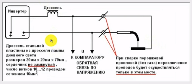
To change the inverter's IVC, there are many schemes, but the easiest way to do this is as follows:
- assemble the device using fluorescent lamp choke according to the scheme below;
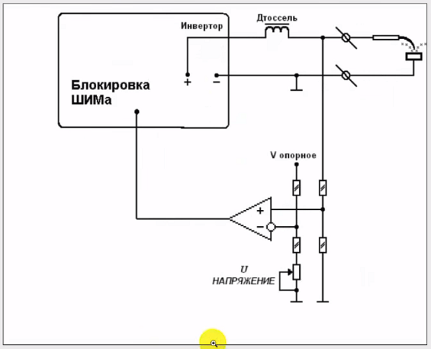
- to connect the assembled device, you will need to assemble another unit as follows;
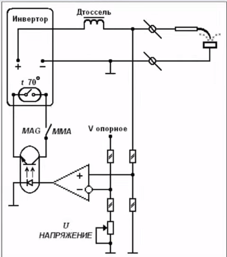
- so that the overheating sensor does not work on the inverter, it is necessary to solder (in parallel) the optocoupler to it, as shown in the following diagram.
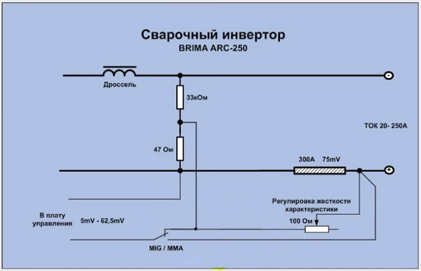
But if the welding current in the inverter is controlled with shunt, then you can assemble a simple circuit of three resistors and a mode switch, as shown below.
As a result, the conversion of the welding inverter into a semiautomatic device will cost 3 times cheaper than the already finished unit. But of course, for self-assembly apparatus, you will need to have some knowledge in the radio industry.
/rating_off.png)