Making a spotter with your own hands
Spotter is quite a useful device that helps to significantly improve the efficiency and speed of work. in car body repair. But this unit has a fairly high cost with simplicity of design. Therefore, many masters prefer to make a spotter from an old transformer or from a welding machine with their own hands.
Content
Appointment of spotter
In car body repair it is often necessary to remove dents, for example, after an accident. Various methods are used for this: pulling out dents with suction cups, leveling the hammer with blows from the back of the part, etc. In the latter case, the part must be removed to eliminate the defect.
Significantly speed up and simplify the process of aligning auto parts allows the use of the spotter. This unit is a kind of resistance spot welding, with the help of which you can weld washers, studs, bolts, hooks and other fasteners to damaged parts of the car body. In the future, they engage in various tools to align dents.
Also spotter can be used for soldering, heating, hardening and precipitation leveling surfaces.
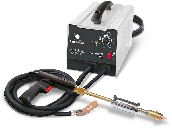
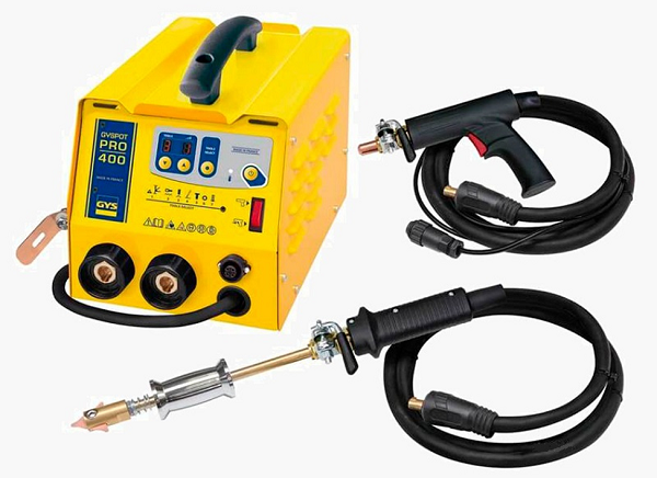
The device and the principle of the spotter
Spotter consists of the following elements:
- welding machine, which can be transformer or inverter type;
- cables (power cable and mass cable);
- welding gun (stadder);
- electrode with an inertial hammer.
When you press a button on the stader, current begins to flow. Depending on the mode chosen, the current supply can be constant or in the form of a single short pulse. Further, the current flows to the electrode, which may have tips of different shapes.
The device works according to the following principle.
- Place on the back of the car, which you want to align, cleaned of paint.You should also strip a small area for connecting the ground cable.
- Any fastener, for example, a washer, is attached to the spotter electrode and welded to the leveling point.
- A tool for alignment clings to the puck, after which the dent is pulled out.
Extrusion of dents can be carried out and without welding fasteners. In this case, a pointed tip is required on the electrode with an inertial hammer. The electrode is applied to the desired location of the part, and the tip is welded to it with a short discharge current. Then, without removing the electrode from the part, they are hit with a hammer in the direction opposite to the tip, thereby pulling a dent (it is impossible to use a reverse hammer on aluminum). After elimination of the defect, the welded end of the electrode breaks off easily.
How and from what to make a spotter
The spotter transformer is noticeably different from the classic welding transformer. In arc welding, the metal is heated by an electric arc, and in the case of point heat, it is released due to the transient resistance at the electrode-metal site.This happens when arc welding, for example, if the wrong mode of operation on the unit. In this case, the electrode sticks to the metal, which can cause damage to the apparatus.
To prevent this, spot welding is carried out in pulsed current mode (up to 1 second). And since arc welding is not required for spot welding, the voltage in the spotter should be minimal (about 6 V), and the current should be high (at least 1000 A).
From the welding machine
It is impractical to make this unit out of the inverter, at least due to the fact that direct current is not required for spot welding. In addition, you have to redo the transformer to achieve high current performance. With such success, you can make a unit for spot welding from scratch. If there is an inverter apparatus, it is better to use it for its intended purpose, and to adapt a conventional transformer welder for the spotter.
As for semi-automatic machines, all universal models of these units already have the function of pulse welding, and they will not need alteration. But if there is a broken, ordinary semi-automatic, then it will need to redo the transformer.
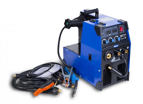
Automatic welding semiautomatic device Aurora
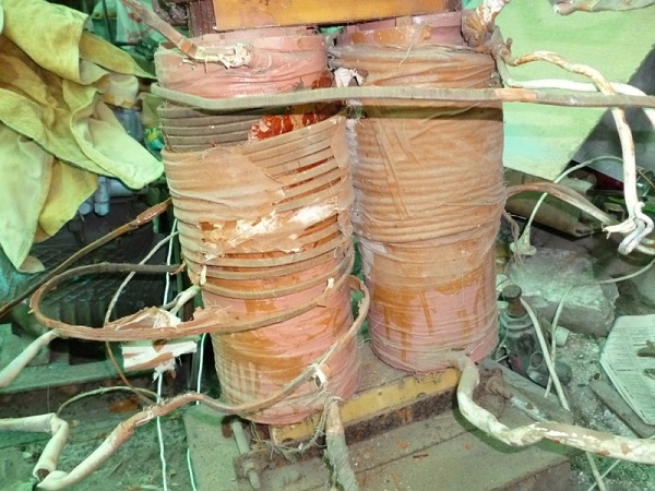
Alteration of the transformer is to remove the secondary winding and winding new. A spotter requires a welding current of 1000 A. If the calculations are based on the assumption that the current density is 8 A per 1 mm2then its section should be about 120 mm2. But winding the wire of this section is quite difficult. Therefore, you can take a tire with a smaller section, for example, 80 mm2if the machine is not going to be used too intensively.
For determining the number of turns do the following.
- Wind up any conductor covered with insulation to the magnetic core. 10 turns will be enough.
- Connect the primary winding to the network, and measure the voltage on the improvised secondary housing.
- The result must be divided by the number of turns, that is, 10. As a result, you will receive a value that determines the number of turns to get 1 V voltage. But since the spotter requires a voltage of 6 V, then by multiplying the obtained value, you can find out the number of turns.
Based on the diameter of the wire with the necessary cross section, you can decidewhether this winding enters the free space between the primary and secondary transformer windings (not yet removed). If there is enough space, then the secondary can not be removed from the magnetic circuit, and the new winding wound over it. In this case, the welder can be used and for electric arc weldingand for scatter.
A modified transformer is not the only detail that is required in order to make a spotter from a welding machine. You need to add to it electronic discharge control unit and a small transformer for powering the module. Below is a diagram of the unit controlling the spotter.
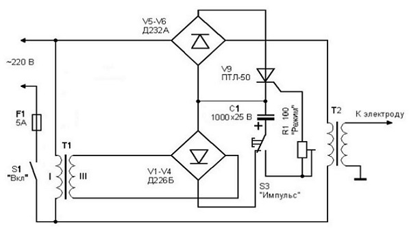
This scheme works as follows.
- When the circuit is closed by the switch S1, the current to the primary transformer T1 starts to flow.
- Next, the capacitor starts charging. It is connected via a closed switch contact to the diode bridge.
- The output transformer T2 will be de-energized until the switch button S is pressed. After that, the voltage from the capacitor through the variable resistor will go to the control electrode of the thyristor.Further, the voltage will go to the primary of the output transformer, after which a pulse with the current required for welding will appear on its secondary winding.
- After the discharge of the capacitor, the module enters its original state. To repeat the impulse, it is necessary to press the switch again.
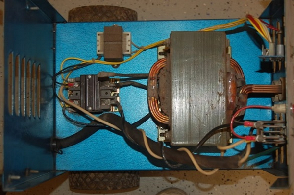
After the control unit is ready, all components are placed. in the plastic or metal case.
From battery
This unit, made of a 12 V battery, is mobile and can operate regardless of the presence of the mains. For the manufacture of the unit will require the following components.
- Standard battery at 12 V and 75 A / h and above.
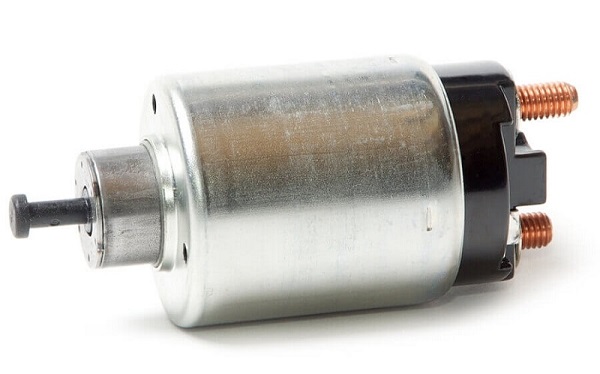
- Retractor relay. You can use the relay from the car starter. It is desirable that it be collapsible, for periodic cleaning of contacts inside it.
- Start button.
- Cables with terminals and welding gun.
Assembly apparatus is carried out according to the scheme below:
- a ground cable is connected to the negative terminal of the battery, which must be in contact with the part prepared for repair;
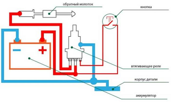
- the first contact of the relay is connected to the positive terminal of the battery;
- the cable to the welding gun is connected to the second relay contact;
- between the first and third (connected to the battery plus) contact of the relay, a start button is set;
- the retractor relay must be connected to ground.
Cable section should be about 100 mm.2, and their length is no more than 1.5 m. The only drawback of this device is that the battery quickly sits down and it takes time to charge it.
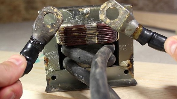
From microwave
To make the device, you need a transformer, extracted from the microwave. But for reliability it will be better if use two coils. Remove the secondary winding from each transformer and wind a pair of coils with a cable of at least 50 mm instead2.
The primary windings of both transformers are connected in parallel. Further, the spotter control module, which was discussed above, is connected to the circuit. You can also simplify the design of the spotter, if the circuit includes a time relay and a retractor relay from the car. How this is done, you can find them out. video.
Important! Despite the low voltage - 6 V and less, the current received at the output of the transformer has huge values, about 1000 A,which represents a great danger to human life. Therefore, both transformer windings must be grounded.
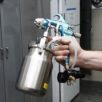
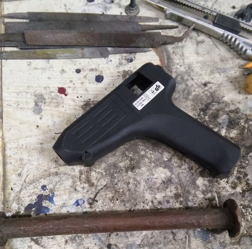
Welding gun
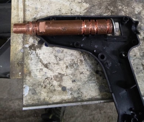
For the manufacture of the welding stick no drawings will be required. Best suited for this purpose glue gun body. You will also need a copper rod with a diameter of about 20 mm.
On one side of the rod is necessary to cut the thread (M14h1, 5). Various welding tips will be screwed onto it. A hole is drilled on the other side and internal thread M8 is cut. This place will be attached cable. Also on the details should make a few groovesso that it is better fixed inside the case.
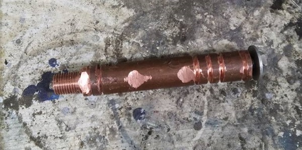
Further, the part is installed in the housing.
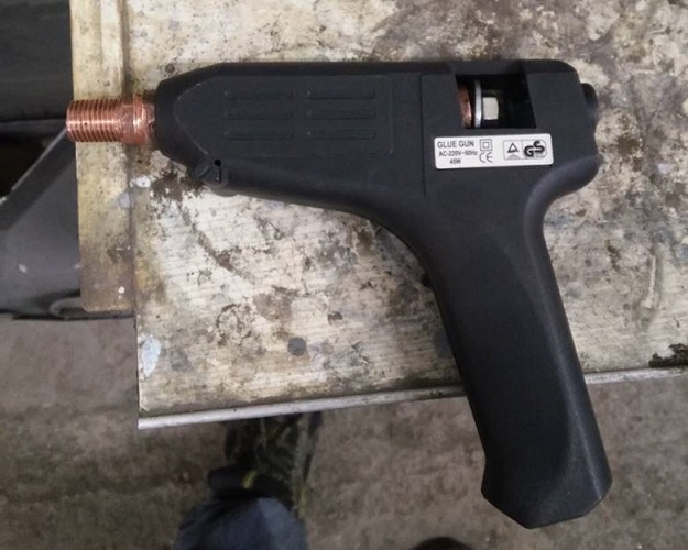
It only remains to find a suitable button, position it in the case and connect it to the electrical circuit of the device.
/rating_off.png)