Repair and maintenance of air compressor do it yourself
The air compressor is a versatile and economical device, without which the operation of various pneumatic equipment used in production and in everyday life is impossible. Compressors can be both stationary and mobile, thereby expanding the scope of use of these units.
Content
Scope of air compressors
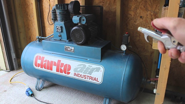
Air compressors are widely used in many areas of human activity. These devices are indispensable for assembly, carpentry, construction and repair work. Also, air vehicles are successfully applied and at home. For example, a household unit can be used for tire inflation, paint work, airbrushing, etc. As a rule, it is a compressor having an electric motor running on 220 V. For professional use better suited rotary oil unit, which has an increased service life and is not demanding of frequent maintenance.
High demand for air compressors and in the industrial field, in industries where the use of compressed air is required.
There are devices with a high degree of air purification. They are used in "clean" industries, for example, in the chemical, pharmaceutical and food industries, as well as in the production of electronics.
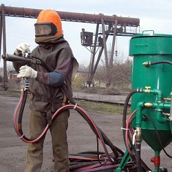
In addition, air compressors have been used in the oil and gas industries, in the mining industry, in the extraction of coal and stone.
How the air compressor works
The device unit for air compression is determined by the type of construction. Compressors are piston, rotor and membrane. The most widespread piston air units, in which the air is compressed in the cylinder due to the reciprocating movements of the piston inside it.
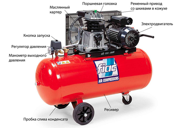
Device layout
The device air piston compressor is quite simple. Its main element is compressor head. By design, it is similar to the cylinder of an internal combustion engine (ICE). Below is a diagram of a piston assembly, in which the device of the latter is well shown.
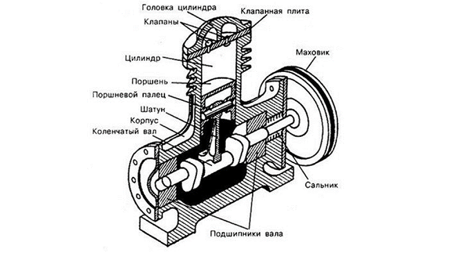
The composition of the compressor unit includes the following elements.
- Cylinder. This is the volume in which air is compressed.
- Piston. Reciprocating movements sucks air into the cylinder or compresses it.
- Piston rings. Installed on the piston and are designed to increase compression.
- Connecting rod. Binds the piston to the crankshaft, giving it a reciprocating motion.
- Crankshaft. Thanks to its design, the connecting rod moves up and down.
- Inlet and discharge valves. Designed for intake and exhaust air from the cylinder. But compressor valves are different from ICE valves. They are made in the form of plates pressed by the spring. The opening of the valves is not forced, as in the internal combustion engine, but because of the pressure drop in the cylinder.
To reduce the friction force between the piston rings and the cylinder in the compressor head oil flows. But in this case, at the outlet of the compressor, the air has impurities of lubricant. To eliminate them on the piston unit set the separatorin which the mixture is separated into oil and air.
If a special purity of compressed air is required, for example, in medicine or in the electronics industry, the design of a piston unit does not imply the use of oil. In such devices, piston rings are made of polymers, and graphite grease is used to reduce friction.
Piston units may have 2 or more cylinders arranged in a V-shape. At the expense of it productivity of the equipment increases.
The crankshaft is driven from the electric motor by belt or direct drive. When a belt drive in the design of the device includes 2 pulleys, one of which is mounted on the motor shaft, and the second - on the shaft of the piston unit. The second pulley is equipped with blades for cooling the unit. In the case of direct drive, the shafts of the engine and piston unit are connected directly and are on the same axis.
Also in the design of a piston compressor includes another very important element - receiver, representing a metal container. It is designed to eliminate the pulsations of air leaving the piston unit, and works as a storage tank.
Thanks to the receiver, it is possible to maintain the pressure at the same level and to evenly expend air. For security on the receiver set emergency relief valve, triggered by increasing the pressure in the tank to critical values.
That the compressor could work in the automatic mode, on it is established pressure switch (pressure switch). When the pressure in the receiver reaches the required values, the relay opens the contact and the engine stops. Conversely, when the pressure in the receiver drops to the established lower limit, the pressure switch closes the contacts,and the unit resumes operation.
Operating principle
The principle of operation of a piston compressor can be described as follows.
- When the engine starts, the crankshaft begins to rotate, transmitting reciprocating movements through the connecting rod to the piston.
- The piston, moving down, creates a vacuum in the cylinder, under the influence of which the intake valve opens. Due to the difference in air pressure, it begins to be sucked into the cylinder. But before entering the compression chamber, the air passes through the cleaning filter.
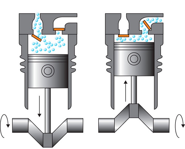
- Further, the piston starts moving upwards. In this case, both valves are in the closed state. At the moment of compression in the cylinder, the pressure starts to rise, and when it reaches a certain level, the exhaust valve opens.
- After opening the exhaust valve, the compressed air is directed to the receiver.
- When a certain pressure is reached in the receiver, the pressure switch is triggered, and the air is suspended.
- When the pressure in the receiver drops to the set values, the pressure switch starts the engine again.
Common faults and their removal
The main problems in the operation of the air compressor, which can be eliminated with your own hands, are the following:
- engine does not start;
- engine buzzing but not starting;
- air (at the outlet) has particles of water;
- drop in the performance of the unit;
- overheating of the compressor head;
- unit overheating;
- knock on the cylinder;
- knock on the crankcase;
- oil leakage from the crankcase;
- flywheel jamming;
- the receiver does not hold pressure;
- unit does not develop momentum.
Unit engine does not start
First of all, when the engine of the unit fails, make sure that there is voltage in the network. Also, do not be superfluous to check the power cable for damage. Next, check the fuses that may burn out if the power supply voltage changes. If there is a fault in the cable or fuses, they should be replaced.
Also affects the engine start pressure switch. If it is configured incorrectly, the unit stops turning on. To check the operation of the relay, you must release the air from the receiver and turn on the device again. If the engine is working, then carry out the correct (according to the instructions) adjustment of the pressure switch.
In some cases, the engine may not start due to thermal relay activation. This usually happens if the unit is operating in intensive mode, almost without stopping. In order for the equipment to start working again, it is necessary to give it some time to cool down.
Engine buzzes but does not start
The buzz of the engine without rotating its rotor may be due to low voltage mains, from- what it lacks the power to run. In this case, the problem can be solved by installing a voltage regulator.
Also the engine is unable to crank the crankshaft if receiver pressure too highand pressure resistance occurs. If this is the case, it is necessary to bleed the air from the receiver a little, then adjust or replace the pressure switch. Increased pressure in the receiver can also occur with a faulty relief valve. It must be removed and cleaned, and in case of its destruction, it must be replaced.
Outgoing air has particles of water
If there is moisture in the air coming out of the receiver, then painting of any surface will fail. Water particles may be present in compressed air in the following cases.
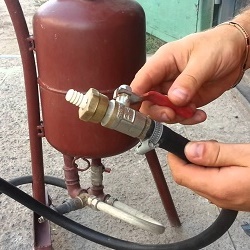
- In the room where the unit operates, high humidity. It is necessary to provide a room with good ventilation or install a moisture separator on the compressor (see the figure below).
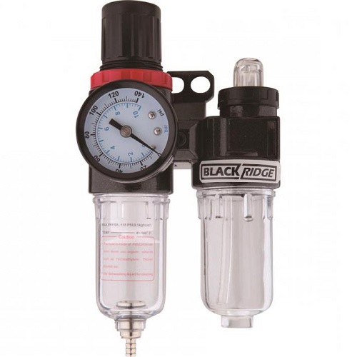
- Accumulated water in the receiver. It is required to regularly drain water from the receiver through the drain valve.
- Faulty water trap. The problem is solved by replacing this element.
Unit performance drop
The performance of the device may be reduced if piston rings burn out or wear out. As a result, the level of compression is reduced, and the device cannot operate in standard mode. If this fact is confirmed when disassembling the cylinder, the worn rings should be replaced.
A drop in performance can also cause valve platesif they are broken or stuck. Faulty plates should be replaced, and clogged ones should be flushed. But the most common cause of a loss of power in an aggregate is air filter cloggingwhich should be rinsed regularly.
Overheating of compressor head
The piston head may overheat when late oil change or when using a lubricant that does not match the one specified in the passport. In both cases, the oil should be replaced with a special compressor, with a viscosity, the value of which is indicated in the passport to the unit.
Also, overheating of the piston head may be caused. over-tightening connecting rod bolts, because of what the oil goes bad on the liners. The fault is eliminated by loosening the connecting rod bolts.
Unit overheating
Normally, the unit may overheat when operating in intensive mode or at elevated ambient temperatures in the room. If the unit still overheats during normal operation and normal indoor temperature, the fault may be caused by clogged air filter. It should be removed and rinsed, then dry well.
Knock on the cylinder
Called breakage or wear of piston rings due to the formation of soot.Usually it appears if you use low-quality oil.
Also a knock on the cylinder may be caused wear on the connecting rod or piston pin bushing. To fix the problem, these parts should be replaced with new ones. When the cylinder and piston are worn, the repair of the air compressor consists in boring the cylinder and replacing the piston.
Knock in the crankcase
The appearance of a knock at the crankcase during operation of the unit is caused by the following failures.
- Connecting rod bolts loosened. It is necessary to tighten the bolts with the required effort.
- Crankshaft bearings out of order. Need to change bearings.
- Worn crankshaft crankshaft crankshaft and connecting rod bushings. The elimination of these faults consists in processing the crankpins to the repair size. Inserts also change to similar parts of the repair size.
Other faults
If oil leaks from the crankcase are detected, then first of all it should be checked and, if necessary, replace seals. If the flywheel does not turn, it means that the piston rested against the valve plate. It is necessary to provide a gap (0.2-0.6 mm) between the piston and the valve plate.If the pressure drops in the receiver, if the unit is turned off, the check valve should be cleaned or replaced.
If the compressor develops poorly, the reason may lie in loosening drive beltswhich tension should be strengthened. Also prevent the engine from developing speed faulty check valve. It should be replaced with a new one.
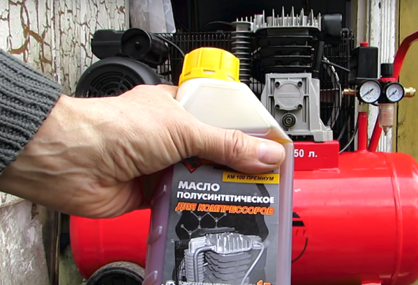
How to change the oil in the air compressor
It is quite difficult to calculate the aggregate hours worked by the unit. But it is still recommended, at least approximately, to keep their records, since the timely replacement of the oil in the device significantly extends its service life. On average, for a new device, the first oil change should be no later than 50 hours. The following maintenance of the compressor for the replacement of lubricant is already carried out through the number of hours indicated in the instructions for the compressor. In each case, depending on the model of the device, this indicator will differ.
Oil for air compressor is better use branddesigned specifically for this equipment. If it is difficult to find branded oil, you can replace it with any compressor oil of the required viscosity.
Important! Simple engine oil should not be poured into the unit!
So, changing the oil in the apparatus for air compression is as follows.
- First of all, you need to disconnect the device from the mains, and completely bleed the air from the receiver. The arrows on all gauges must be at zero.
- Make a container from a plastic bottle into which the lubricant will flow.
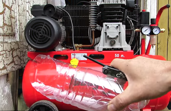
- Substitute the container under the hole to drain the grease and unscrew the nut-cap that closes it. Fine, grease should not be too light or dark. Light grease says that it gets moisture. Too dark oil - the result of overheating of the unit.
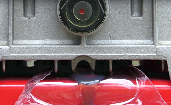
- After the lubricant stops flowing from the crankcase, re-tighten the nut.
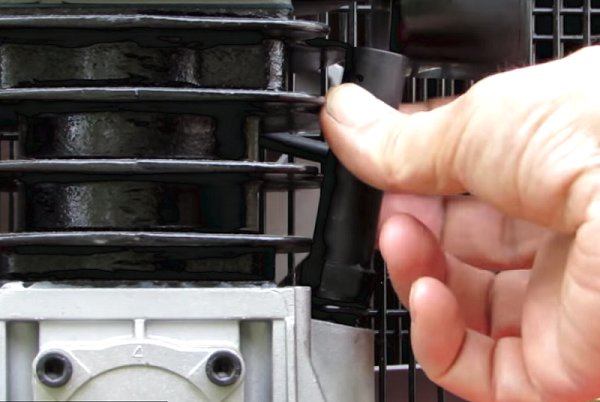
- Next, unscrew and remove the breather from the filler hole in the crankcase.
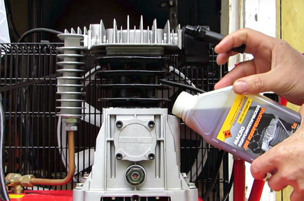
- Pour grease into crankcase. It is more convenient to pour oil through a watering can to prevent spilling. Fill with the amount of grease to reached the benchmark in the viewing window.
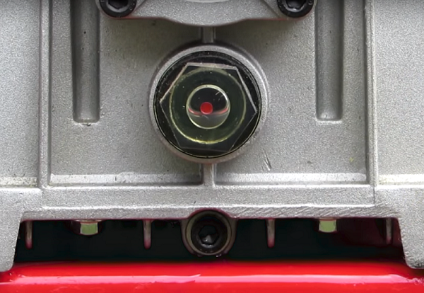
In the future, you should constantly monitor the level of oil in the crankcase, and, if necessary, top it up.
/rating_off.png)