Adjusting the pressure in the pump station with a hydroaccumulator
To make an autonomous water supply system in a small private house, a conventional pump, borehole or surface, with suitable performance characteristics will suffice. But for a house in which more than 4 people live, or for a 2-3-story dwelling it will be necessary to install a pumping station. This equipment already has factory pressure settings, but sometimes they need to be adjusted. When adjustment of the pumping station is required, and how to do it, it will be described below.
Content
Device pumping station
In order to properly adjust this pumping equipment, you must have at least a minimal idea of how it works and what principle it works. The main purpose of pumping stations consisting of several modules is to provide drinking water to all points of water intake in a house. Also, these units can automatically increase and maintain the pressure in the system at the required level.
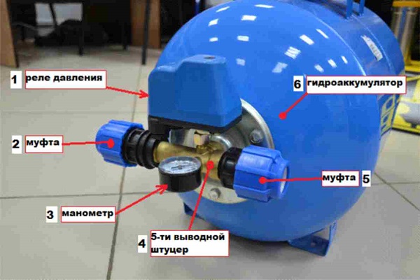
Below is a diagram of a pump station with a hydroaccumulator.
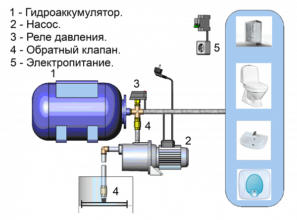
The composition of the pumping station includes the following elements (see figure above).
- Accumulator. Made in the form of a sealed tank, inside which is an elastic membrane. In some containers, instead of a membrane, a rubber bulb is installed. Thanks to the membrane (pear), the hydraulic tank is divided into 2 compartments: for air and for water. The latter is pumped into a pear or into a part of a tank intended for liquid. The connection of the hydroaccumulator occurs in the section between the pump and the pipe leading to the intake points.
- Pump. May be superficial or borehole. The type of pump must be either centrifugal or vortex. Vibrating pump station can not be used.
- Pressure switch. A pressure sensor automates the entire process by which water is pumped from a well into an expansion tank.The relay is responsible for switching the pump motor on and off when the required compression force is reached in the tank.
- Check valve. Prevents fluid from escaping from the accumulator when the pump is turned off.
- Power supply To connect the equipment to the electrical network, it is necessary to stretch a separate wiring with a cross section corresponding to the power of the unit. Also in the electrical circuit should be installed protection system in the form of machines.
This equipment works on the following principle. After opening the tap at the water intake point, water from the accumulator begins to flow into the system. At the same time, a reduction in compression occurs in the tank. When the compression force drops to the value set on the sensor, its contacts close and the pump motor starts working. After the cessation of water consumption at the point of water intake, or when the compression force in the accumulator increases to the required level, the relay trips to turn off the pump.
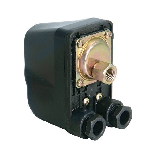
Device and principle of operation of the pressure switch
The device of the pressure switch of the pump station is not difficult. The design of the relay includes the following elements.
- Housing (see picture below).
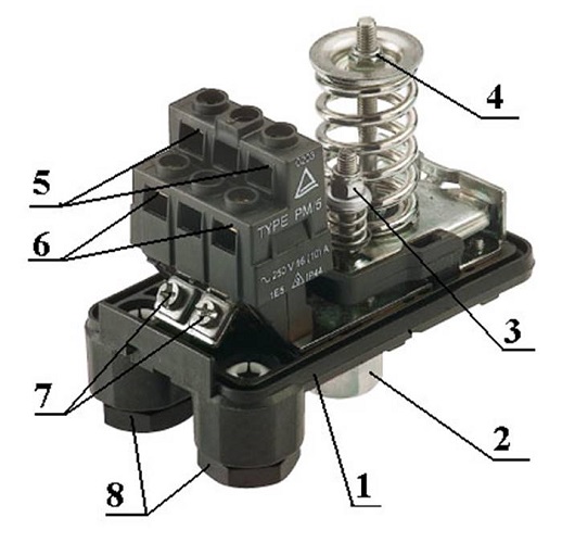
- Flange for connecting the module to the system.
- Nut, designed to adjust the shutdown of the device.
- Nut regulating the force of compression in the tank at which the unit will turn on.
- The terminals to which the wires are connected, coming from the pump.
- Place to connect the wires to the mains.
- Grounding terminals.
- Couplings for fastening electrical cables.
Bottom relay has a metal cover. If you open it, you can see diaphragm and piston.
The principle of operation of the pressure switch following. With increasing compression force in the chamber of the hydraulic tank, designed for air, the relay membrane bends and acts on the piston. It starts moving and engages the relay contact group. The contact group having 2 hinges, depending on the position of the piston, either closes or opens the contacts through which the pump is energized. As a result, when the contacts are closed, the equipment starts up, and when they are opened, the unit stops.
When you want to adjust the relay
As mentioned above, the relay automates the process of pumping fluid into the water supply system and into the expansion tank. Most often, pumping equipment purchased in finished form already has basic relay settings. But there are situations when urgent pressure control of the pumping station is required. It is necessary to perform these actions in the following cases:
- after starting the pump motor, it immediately turns off;
- after shutting down the station, there is a weak pressure in the system;
- when the station is working in the hydraulic tank, an excessive compression force is created, as evidenced by the pressure gauge, but the device does not turn off;
- the pressure switch does not operate, and the pump does not turn on.
Most often, if the unit has the above symptoms, repair of the relay is not required. You just need to properly configure this module.
Preparation of hydraulic tank and its adjustment
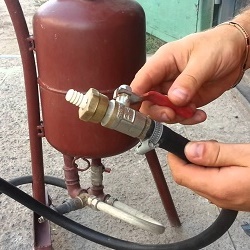
Before entering the hydroaccumulators on sale in them at the factory pumped air at a certain pressure. Air is pumped through the valve installed on the tank.
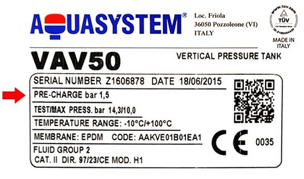
On average, the pressure in the pumping station should be as follows: in hydraulic tanks up to 150 liters. - 1.5 bar, in expansion tanks from 200 to 500 liters. - 2 bar.
Under what pressure is the air in the hydraulic tank, you can learn from the label glued to it. In the following illustration, the red arrow indicates the line,which denotes the air pressure in the accumulator.
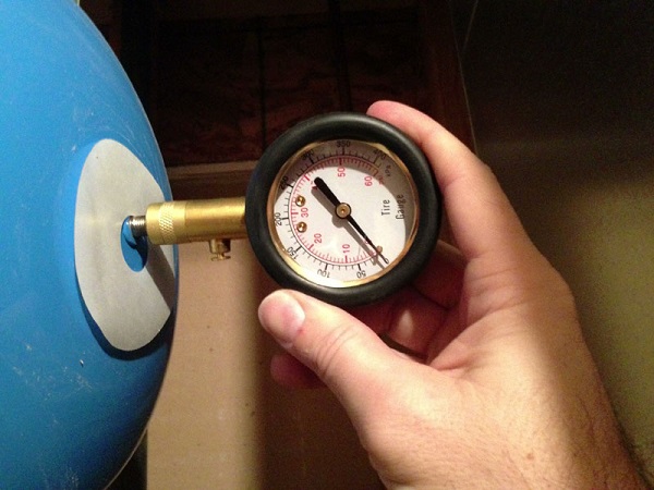
Also, these measurements of the compression force in the tank can be made using car gauge. The measuring device is connected to the spool of the tank.
To begin to regulate the compression force in the hydraulic tank, it is necessary to prepare it:
- Disconnect equipment from the power supply.
- Open any tap installed in the system and wait for the moment when the fluid stops flowing from it. Of course, it would be better if the crane is located near the drive or on the same floor with it.
- Next, measure the compressive force in the tank using a pressure gauge, and remember this value. For small volume drives, the indicator should be around 1.5 bar.
In order to properly adjust the drive, you should take into account the rule: the pressure that causes the relay to activate the unit should turn on the force in the drive by 10% more than the compression force. For example, a pump relay switches the engine on at 1.6 bar. This means that it is necessary to create an appropriate force of air compression in the accumulator, namely, 1.4-1.5 bar. By the way, the coincidence with the factory settings here is not accidental.
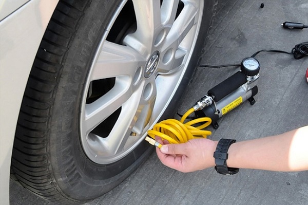
If the sensor is configured to start the station engine with a greater than 1.6 bar compression force, then, accordingly, the drive settings change.To increase the pressure in the latter, that is, to inflate the air, you can, if you use pump for tire inflation.
Pressure switch setting
There are cases when the default sensor settings do not suit the users of pumping equipment. For example, if you open the tap on any floor of the building, you can see that the water pressure in it is rapidly decreasing. Also, installation of some systems that purify water is not possible if the compression force in the system is at a level of less than 2.5 bar. If the station is set to turn on at 1.6-1.8 bar, then the filters in this case will not work.
Usually, setting up a pressure switch with your own hands is not difficult and is performed according to the following algorithm.
- Record gauge readings when the unit is turned on and off.
- Unplug the station's power cord or unplug the machine.
- Remove the cover from the sensor. Usually it is fixed with 1 screw. Under the lid can be seen 2 spring screws. The one that is more responsible for the pressure at which the station engine starts.Usually near it there is a marking in the form of the letter “P” and arrows are drawn with “+” and “-” signs drawn near them.
- To increase compression force, turn the nut towards the “+” sign. Conversely, to reduce it, you need to twist the screw to the “-” sign. Make one turn of the nut in the desired direction and start the machine.
- Wait until the station turns off. If the pressure gauge does not suit you, then continue to rotate the nut and turn on the device until the pressure in the accumulator reaches the desired value.
- The next step is to configure the moment of shutting down the station. A smaller screw with a spring around it is designed for this. Near it is the marking “ΔP”, as well as arrows with the signs “+” and “-” are drawn. Setting the pressure regulator to turn on the device is the same as to turn off the device.
On average, the interval between the compression force at which the sensor turns on the station engine and the value of the compression force when the unit stops is between 1-1.5 bar. In this case, the interval may increase if shutdown will occur at large values.
For example, the unit has factory settings at which Pon = 1.6 bar, and Poff = 2.6 bar. From this it follows that the difference does not go beyond the standard value and is equal to 1 bar. If you want for some reason to increase Poff up to 4 bar, then it is necessary to increase the interval to 1.5 bar. That is, Pon should be about 2.5 bar.
But increasing this interval will increase and pressure drop in the water supply system. Sometimes this can cause discomfort, since you have to use more water from the tank to turn on the station. But due to the large interval between Pon and Poff turning on the pump will occur less frequently, which will increase its resource.
The above manipulations with the settings of the compression force are possible only with the availability of equipment of the appropriate power. For example, in those. passport to the device indicated that it can issue no more than 3.5 bar. So, tune it Poff = 4 bar does not make sense, since the station will work without stopping, and the pressure in the tank will not be able to rise to the required value. Therefore, in order to obtain a pressure in the receiver of 4 bar and above, it is necessary to purchase a pump of the appropriate capacity.
/rating_off.png)