How does the gas column work
To address the issue of providing a dwelling with hot water, often the choice is made on a gas flow type water heater. But, in order to choose a good model from the many on the market, it is necessary to have at least minimal knowledge about the device and the principle of operation of the gas water heater.
Content
Unit device
Gas water heaters, regardless of the manufacturer, have similar components, the presence of which in different models may differ slightly. For example, consider the device gas column Neva.
Device apparatus outside
Diagram of the gas column is shown in the figure below.
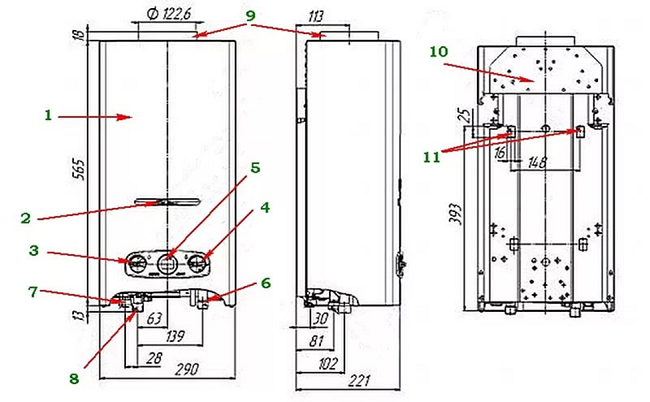
Diagram of the gas column
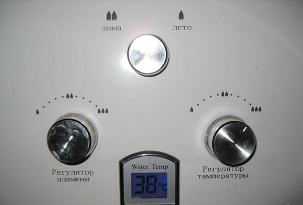
The front and sides of the water heater are covered with a metal casing (1). On the facade of the apparatus there is viewing window (2) for visual control over the operation of the unit. The following regulators are located under the window: a knob regulating the gas flow (3) and a water flow regulator (4). Between the handles is an LCD display (5), which displays the temperature of the water flowing to the consumer.
At the very bottom of the apparatus are nozzles for supplying water and its output, as well as for supplying gas. On the right side of the water heater there is a nozzle (6) to which cold water is connected from the water supply system, and on the left - a pipe (7) is connected to drain the heated liquid. Next to it, but a little closer to the center, there is a pipe (8). It connects to the hose connecting the column to the gas line, and in some situations - to gas bottle. At the very top of the water heater, there is a flange (9) for connecting the flue gas pipe (chimney).
All elements of the unit are fixed on a metal base (10), performing the function of the rear wall of the apparatus. It made 2 holes for hanging the unit on the wall with brackets.
A similar design has a new model of a gas column Astra.
Internal unit arrangement
Now we will consider how the gas column is arranged from the inside, with the outer casing removed.As already mentioned above, the pipes numbered 6, 7 and 8 are designed for connecting cold water, draining heated and connecting gas.
The water unit of the unit (12) is connected to the water supply pipe (6). A stem (13) emerges from the water block, on which a handle for adjusting the water pressure is attached. Below is a cylindrical part (14), which has a notch on the walls. It performs the function of a plug, extracted to drain the liquid from the apparatus, if it is necessary to repair it. Also, the cork has a safety valve that opens with an overpressure in the water supply system.
In the center of the unit is electronic control unit (sixteen). From him in different directions leads wires leading to the various elements of the unit and sensors.
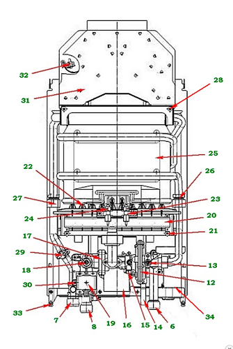
Device speakers inside
On the left, symmetrically to the water block, there is a gas one (17). Both modules and assembled so that they represent a single structure. From it, as well as from the water one, the rod (18) comes out to adjust the gas supply. A valve (19) (electromagnetic) is located in the middle between the gas pipe and the regulating valve.
There is also a microswitch (15) on the gas unit, which is pressed by a special pusher when it is turned off. Above can be seen collector (20), connected to the gas block by means of a nozzle fitted onto the flanges.The collector is attached to the body with 2 screws (21). Nozzles are located at the rear of the manifold. Through them gas is supplied to the burner (22), which has 10 rows. On the front of the collector there is a pair of elements that are similar in appearance but fulfill different roles. On the right is a spark-forming candle (23), igniting the burners, and on the left is a flame sensor (24).
Above the collector is copper heat exchanger (25). It just gives off the heat received from the combustion of gas passing through it to water. A water unit (26) is connected to the heat exchanger on the right, and a branch pipe for draining heated water (27) on the left side. The heat exchange module is fixed to the unit housing with the help of 2 screws (28). On the pipe for removal of heated water is installed 2 sensors. The upper (29) protects the water heater from overheating, and the one below (30) serves as a thermometer. From it go the wires to the LCD display mounted on the housing of the unit.
A device for removal is installed at the top of the machine. waste combustion products (31). Thanks to a system of bridges of various shapes, the flow of hot exhaust gases is directed towards the flue duct. A thrust sensor (32) is installed on the left, which is connected to the overheating sensor (29) by means of an electrical circuit.At the bottom of the water heater body there is a block (34) for 2 batteries (batteries). For fastening the outer casing of the apparatus on both sides of the case, there are places for screwing in screws (33).
The internal layout of the gas column Oasis does not differ from the above, except that the presence of the switch "winter-summer" on the front panel. It is designed to turn off half of the operating burners in the summer to save gas.
Principle of operation
To understand the principle of operation of the gas column, you must first consider what kind of security system it is equipped with. When the unit is in the off state, the control unit (16) does not receive electricity, since the circuit is broken in the microswitch (15). The switch plate is pressed by the pusher, and while this is happening, it is in the off state.
Solenoid valve (19) is also closed and blocks the flow of gas from the inlet pipe, because it does not receive power. But this is not the only place that covers the gas - it is also blocked by spring valvewhich is located in the gas module (35). The non-operating state of the valve is characterized by pressing the gasket plates to the seat, which ensures the complete shut-off of the supply of combustible mixture to the manifold.
The water section consists of a two-chamber module (36), colloquially called a “frog”, with elastic rubber membrane. With the help of a special channel camera “frogs” can communicate. When the water supply is turned off, the pressure in the chambers is equalized, and the membrane is in the equilibrium position.
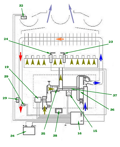
The principle of operation of the gas column
Water to the heat exchanger is supplied through the bottom of the chamber. At the top there is a rod with a plate made of plastic, which is adjacent to the membrane. The stem exits through the hole in the middle, towards the gas block. Opposite this rod, in the gas module, is the same, but connected to the spring valve, to which the plunger is attached, coming from the switch.
What happens when the water starts
How does the gas column work if you open the water? When opening at the point of consumption (water intake) of the tap with water, the following occurs.
- As the fluid flows through the frog, a vacuum is created in its chamber. The rubber membrane under the action of high pressure is curved and pushes the plate. The latter transmits the pushing movement to the stock.The stem of the water module pushes the opposite end of the stem of the gas module (37).
- Further, the pusher, having a connection with the rod, no longer holds the switch plate, and it is released. In this case, the switch closes the circuit, and the power supply starts to flow into the electronic control module from the section with batteries.
- The movement of the rod also causes the spring of the mechanical valve to be released, as a result of which the plate moves away from the seat and the gas supply channel to the manifold becomes open.
- The solenoid valve, receiving power from the battery, opens and does not prevent the passage of gas through the spring valve towards the collector.
- Meanwhile, the control unit generates and sends an electric pulse to the candle (23) to create spark dischargeable to kindle a flame. At normal operation of all nodes - the burner lights up.
The ignition process is monitored by an ionization sensor (24). In the case when the burner does not light up for 6-7 seconds, in order to avoid accumulation of a high concentration of an explosive mixture, the electronic module, not receiving a pulse from the sensor, will shut off the gas supply. In the presence of combustion, the sensor will generate a pulse to turn off the spark plug. If the flame goes out after the start of operation of the water heater, then the impulse from the sensor will stop coming to the control module, after which it will immediately respond to this by shutting off the gas using an electromagnetic valve.
It is possible to perform all these functions in the gas column only if one condition is met: the circuit between the two sensors should not be broken, namely, between the temperature sensor of the outlet water control (29) and the draft sensor (32). These relays are connected in series, and their contacts are in the closed state when the sensors are in working condition. Therefore, in order for the control module to receive power, both sensors must close the circuit.
If in the chimney block weak traction is formed, then the combustion products, due to the special design of the gas exhausting unit, cannot pass towards the central channel, and are sent to the side cavities. Since the temperature sensor is located on the left, it will “detect” a sudden rise in temperature by breaking the power supply circuit to the control module.This will stop the supply of combustible mixture and turn off the burners.
By analogy, the relay is activated, which is placed on the nozzle for draining the heated water from the heat exchanger. When the water heats up to 90 ° C, and this is considered a critical level, the power supply circuit of the electronic unit will be broken.
Work when turning off the water
When the water supply is turned off, the following happens.
- The pressure in the frog chambers is balanced. The return of the membrane from the rubber to the place causes the movement of the plate connected to the pusher in the corresponding direction to the initial position.
- When the rod returns, the disc valve relieves to reliably shut off the fuel supply.
- At the same time, the pusher starts to press the switch plate, as a result of which the circuit supplying the control module is broken.
- Since the solenoid valve does not receive electricity after the control unit has been switched off, it also closes.
Thus, turning off the water triggers a chain of processes that automatically turn off the water heater. For clarity, the photo below shows the main components of the unit (bottom view)affecting its operation (the numbering has been saved and a new position has been added, at number 40, the microswitch pusher).
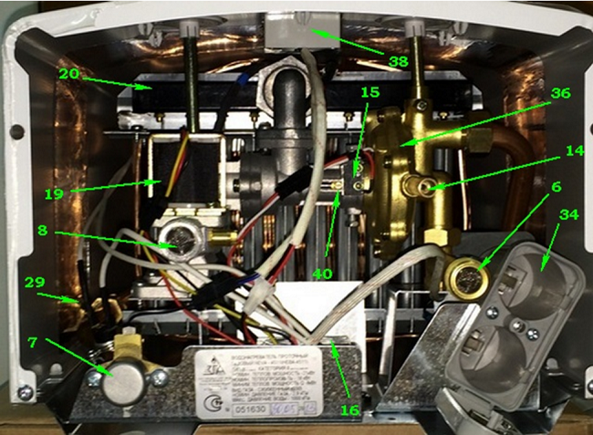
The main nodes of the gas column
The information display (38) is also connected to the electronic control circuit of the water heater and the temperature sensor (39) on the outlet nozzle using several wires. Display only plays informational role and does not participate in the operation and adjustment of the gas water heater.
The unit is able to work even when the LCD is turned off, for example, after removing the outer casing to which it is attached.
Summarizing the above, we can say that the geyser is quite complex and reliable in the operation of the device. Over the many years of the existence of these units, their design has changed only slightly, except that electronic control and monitoring units have been used in devices for more convenient control.
/rating_off.png)