How to install, run and configure the pumping station
Autonomous water supply is a priority engineering structure in a private house, especially if there is no centralized water supply nearby. To ensure a constant supply of water to the house, installation and connection of a pumping station will be required. Although this equipment is not cheap, you can still save a significant amount if you install and connect the station yourself.
Content
Variants of the installation site of the pumping station
When planning to assemble and connect the pumping station to the water supply system in the house, the following points should be considered.
- The unit must be located near a water source. This will ensure stable absorption of fluid from the source and smooth operation of the station. If the equipment is placed far from the well (well), it will not be able to pump water and will fail.
- To install the equipment you need to pick a dry, well-ventilated and warm place.
- The device should not touch any objects and walls.
- Access to equipment for routine inspection and repair work should be free.
Important! When installing a station with a surface pump, consider the high level of noise that it creates when working.
Based on the foregoing, there may be several options for installing the unit.
In the House
For the correct operation of the station the most ideal option is a heated room.. Well, if in a private house there boiler room with good noise insulation.
In extreme cases, water supply equipment can be installed. in the hallway, bathroom, hallway or in the pantry. But these rooms should be located as far as possible from the rest rooms (bedroom, living room). The device is placed in a cabinet or closed with a special casing that provides sound insulation.
In the basement
Most often, pumping equipment is installed in the basement of the house or in the basement. Sometimes the unit is installed under the floor, providing access to it through the hatch. In any case, the place where the apparatus is being installed should be with good sound and water insulation. It should also be warm enough so that the temperature in it does not fall below 0 ° C during the winter period.
In the well
To place the station in the well, it is installed small platform. It is fixed below the freezing ground limit.
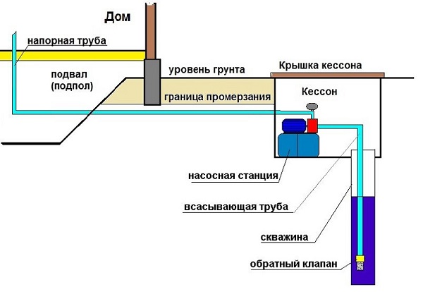
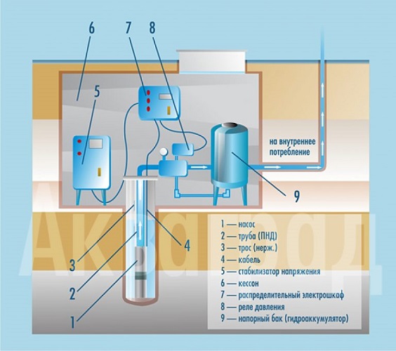
In caisson
In this case, in order to properly install the pump, a small room (caisson) is built around the water source, of sufficient width and depth (below the freezing boundary).
Caisson top covered with a hatchthrough which the maintenance of the unit. In winter, the lid is well insulated.
Thanks to the pit, it is possible to provide autonomous water supply with a surface pump, even if the water level from the ground is at a depth of 9-11 meters.
In the case of the assembly station with submersible pump There is no need to worry about soundproofing, since the unit is located deep underground, and its operation is almost unheard of. All elements of the station are installed in any heated room, and the pump itself - in the well or well. This version of the assembly of the pumping station is well suited for giving.
Options for tying pumping station
By tying a pumping station, it is customary to mean connecting pumping equipment to a piping system and other elements.
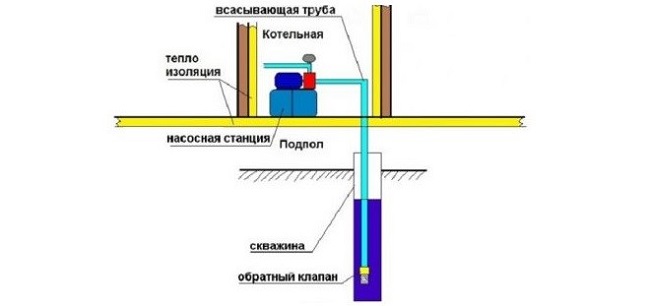
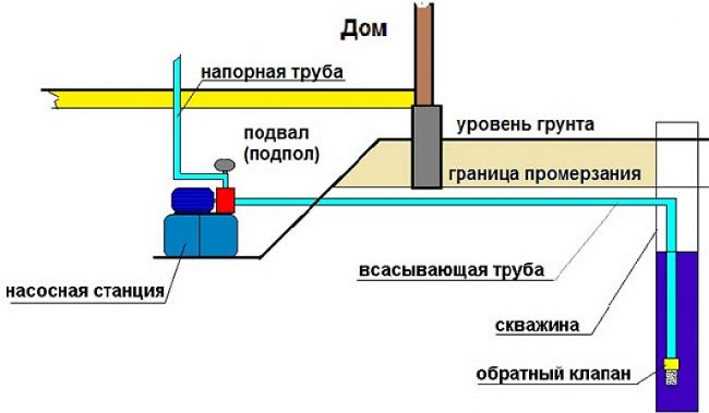
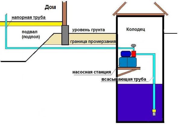
Connecting the station to the well
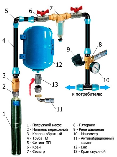
For installation of the pumping station in the caisson or in the house use the same scheme. The beginning of the scheme is supply pipewhich is laid underground, at a depth below the level of soil freezing. At the end of the pipeline install a coarse filter, consisting of a fine mesh. After the filter is installed check valveprevents reverse flow of water when the pump is turned off. Below is a flow chart (drawing) of a pumping station.
Important! This wiring diagram of the pumping station involves the location of the supply pipe inside the foundation of the house. He should be well insulated in this place.
Next, the feed pipe is connected to the pump with a coupling. The following figure shows a simple layout of the pumping station.
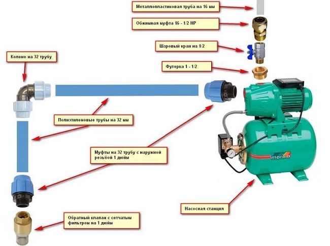
The above assembly scheme can be improved (see figure below) if you want to connect to the unit several points of water intake.
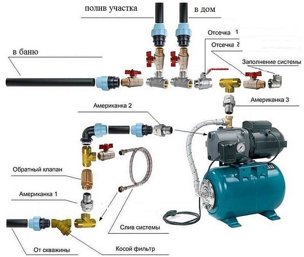
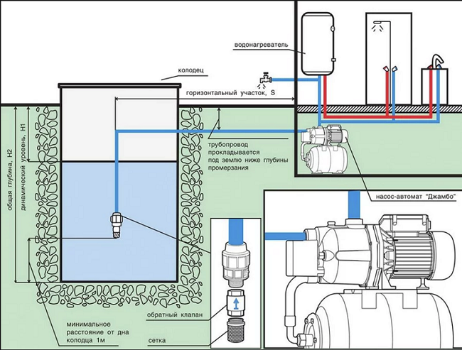
Well connection
To connect a station with a surface pump to a well in which the dynamic water level is below 8 meters, you will need to install it in a caisson with a depth of about 2 m. If a submersible pump is used, a hydroaccumulator and various electrical equipment, such as a voltage stabilizer, an automation system, etc., can also be placed in the caisson.
Automation of the process of water in the pressure tank is implemented via pressure switch, which turns on and off the pump at a certain pressure in the system. Also, to automate the operation of the pump, you can independently make the control unit. Below is a circuit diagram of such a unit.
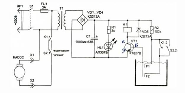
The control unit operates according to the following principle:
- relay K1, turns the unit on and off;
- switch S1, is responsible for the mode of operation (water-drainage);
- monitoring the water level in the storage tank, “monitored” sensors F1 and F2;
- the power is turned on by the switch S1 provided that the water level is below the sensor F1 - in this case, the unit is turned on via contacts K1;
- when the water reaches the F1 sensor, the VT transistor will open1then the relay K will turn on1.
This scheme uses a low-power transformer from a conventional broadcast receiver. The voltage supplied to the capacitor must be at least 24 V. Any diode can be used, with a reverse voltage greater than 100 V and a current of 1 A.
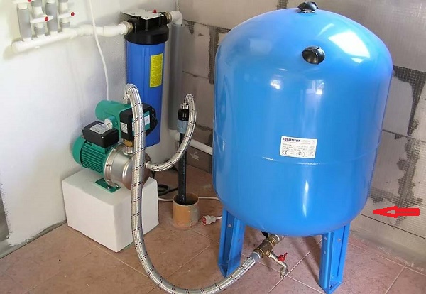
The station is assembled with a submersible borehole pump according to the scheme below.
Connecting the station to the water supply system
Sometimes it becomes necessary to use a pumping station, even when a centralized water supply system is connected to the house. A station with a storage tank is usually installed if low pressure in water supply system. Also, this equipment will be indispensable if the water supply through the highway is carried out at certain hours.
The pumping station is connected to the centralized water supply as follows:
- bring the pipe from the centralized highway to the storage tank;
- connect the pump intake pipe to the tank;
- the outlet pipe from the pump should be connected to the house water supply system;
- route and connect electrical wiring to the unit;
- Perform a trial run of the device, then adjust the equipment to the desired performance.
Rules for starting and setting up equipment
Before the first start-up of pumping equipment, it is first necessary to prepare a hydroaccumulator, as the stability of the entire water supply system depends on a properly selected pressure. A high pressure in the tank will provoke frequent switching on and off of the unit, which will not in the best way affect its durability. If there is a low pressure in the air chamber of the tank, this will lead to excessive stretching of the rubber bag with water, and it will fail.
Hydraulic tank is prepared as follows. Before pumping air into the tank, make sure that the pear inside it is empty. Next, check the tank pressure with an automobile gauge. As a rule, new tanks are pumped with air at the factory.Hydraulic tanks up to 25 liters should have a pressure in the range of 1.4-1.7 bar. In containers of 50-100 liters, the air pressure should be in the range from 1.7 to 1.9 bar.
First station launch
In order to properly perform the first start of the pumping station, perform the following steps step by step.
- Unscrew the plug that covers the water hole located on the unit housing. On some devices, instead of a plug, there may be a valve. It should be open.
- Next, fill the suction pipe and pump with water. Stop pouring the liquid should, when it begins to flow out of the hole for the Gulf.
- When the suction pipe is full, close the opening with the stopper (close the valve)
- Connect the station to the mains and turn it on.
- To remove the remaining air from the equipment, open the tap at the point of intake closest to the pump.
- Let the unit work for 2-3 minutes. During this time, water should flow from the tap. If this does not happen, you should turn off the pump and refill water, then start the pumping station.
Automation setting
After a successful launch, you need to check and configure the operation of the automation. New pressure switch has factory settings upper and lower pressure thresholdat which it turns on or off the pump. Sometimes it becomes necessary to change these values, putting them at the desired on-off pressure.
Adjustment of automation is as follows.
- Turn off the unit and drain the water from the accumulator.
- Remove the cover from the pressure switch.
- Next, you must start the pump to start to collect water in the hydraulic tank.
- When the device is turned off, record the readings of the pressure gauge - this will be the value upper shutdown threshold.
- After that, open the tap at the most distant or highest point of the water intake. As water flows out of it, the pressure in the system will begin to decrease, and the relay will turn on the pump. The manometer readings at this point will mean lower threshold. Record this value and find the difference between the upper and lower thresholds.
Normally, the switch-on pressure should be 2.7 bar, and the shut-off should be 1.3 bar. Accordingly, the pressure difference is 1.4 bar. If the resulting figure is 1.4 bar, then nothing needs to be changed. At low pressure the unit will often turn on, which will cause premature wear of its components. If the pump is too high, the pump will work in a more benign mode, but at the same time the difference in head will be obvious: it will be unstable.
When testing the operation of the relay, please note with what pressure water flows from the tap. If the pressure is weak, then you need to adjust the pressure. In this case, the pressure in the system should be higher. To raise it, you must turn off the machine and slightly tighten the nut that presses the large spring of the pressure switch. To reduce the pressure, the nut must be loosened.
/rating_off.png)