Connecting the pressure switch to the compressor and setting it up
One of the main indicators of air compressors is the working pressure. In other words, this is the level of air compression created in the receiver that needs to be maintained within a certain range. Manually, referring to the indicators of the manometer, it is inconvenient to do this, therefore, the compressor automation unit is responsible for maintaining the required level of compression in the receiver.
Content
Device and principle of operation of the automation unit
To maintain the pressure in the receiver at a certain level, most air compressors have an automation unit, pressostat.
This piece of equipment turns the engine on and off at the right time, not allowing the level of compression in the storage tank to be exceeded or its value too low.
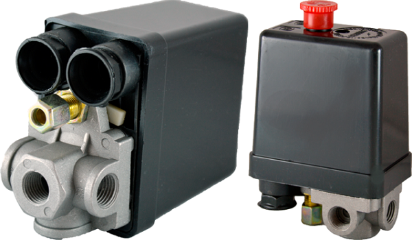
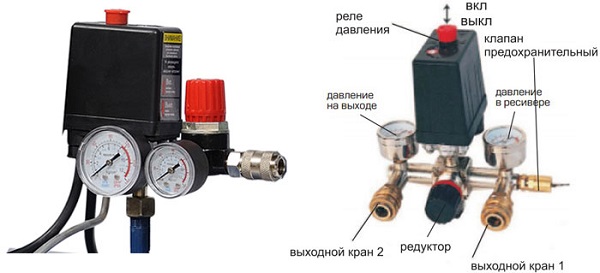
The pressure switch for a compressor is a unit containing the following elements.
- Terminals. Designed to connect to the relay electrical cables.
- Springs. Mounted on adjusting screws. The level of pressure in the receiver depends on the strength of their compression.
- Membrane. Installed under the spring and compresses it under the action of compressed air.
- Power button. Designed to start and stop the unit.
- Connection Flanges. Their number can be from 1 to 3. The flanges are used to connect the compressor on relay to the receiver, as well as to connect a safety valve with a pressure gauge to them.
In addition, the automation of the compressor may have additions.
- Discharge valve. Designed for pressure relief after the engine is forced to stop, which facilitates its restart.
- Thermal relay. This sensor protects the motor windings from overheating by limiting the amperage.
- Time relay. Installed on compressors with a three-phase motor. The relay disconnects the starting capacitor a few seconds after the engine starts.
- Safety valve. If a failure occurs in the relay, and the compression level in the receiver rises to critical values, in order to avoid an accident, the safety valve will operate, releasing the air.
- Gearbox. Pressure gauges are installed on this element to measure air pressure. The gearbox allows you to set the desired level of compression of the air entering the hose.
The principle of the pressostat as follows. After starting the engine of the compressor in the receiver begins to increase pressure. Since the air pressure regulator is connected to the receiver, compressed air from it enters the membrane unit of the relay. The membrane bends upward under the action of air and compresses the spring. The spring, compressed, activates the switch, which opens the contacts, after which the engine of the aggregate stops. When the compression level in the receiver decreases, the membrane installed in the pressure regulator bends downwards. The spring opens in this case, and the switch closes the contacts, after which the engine starts.
Wiring diagram of the pressure switch to the compressor
The connection of the relay controlling the compression ratio of air can be divided into 2 parts: electrical connection of the relay to the unit and connection of the relay to the compressor via connecting flanges. Depending on which engine is installed in the compressor, for 220 V or 380 V, there are different schemes for connecting the pressure switch. I am guided by these schemes, subject to the availability of certain knowledge in electrical engineering, you can connect this relay with your own hands.
Relay connection to 380 V mains
To connect the automation to the compressor, operating from 380 V mains, use magnetic switch. Below is a diagram of the connection of automation to the three phases.
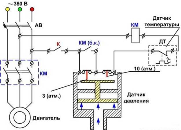
In the diagram, the circuit breaker is indicated by the letters “AB”, and the magnetic starter is designated “KM”. From this scheme, it can be understood that the relay is set to a switching pressure of 3 atm. and shutdown - 10 atm.
Connect the pressostat to a network of 220 V
The relay is connected to the single-phase network according to the diagrams given below.
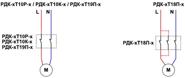
Various schemes are indicated on these schemes. model pressostatov series RDKwhich can be connected in this way to the electrical part of the compressor.
Pressostat connection to the unit
Connecting the pressure switch to the compressor is quite simple.
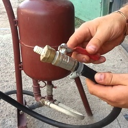
- Screw the pressure switch on the receiver's pipe, using its threaded central hole. Recommended for better thread sealing. use a fum-tape or liquid sealant. Also, the relay can be connected to the receiver via a reducer.
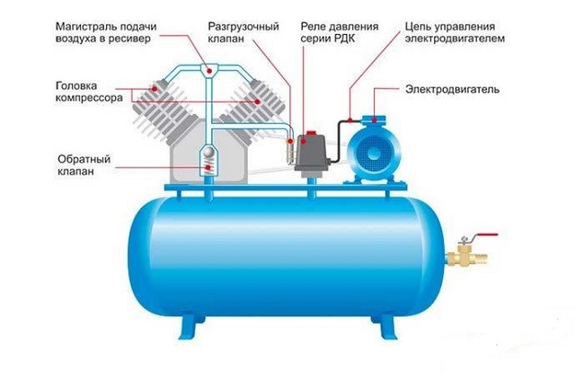
- Connect to the smallest output from the relay, if present, unloading valve.
- To the remaining outputs from the relay, you can connect either a pressure gauge or safety relief valve. The latter is installed on a mandatory basis. If a pressure gauge is not required, the free output of the pressure switch must be plugged with a metal plug.
- Further, wires from the power supply network and from the engine are connected to the sensor contacts.
After the full connection of the pressure switch is completed, you need to configure it to work properly.
Compressor pressure adjustment
As mentioned above, after creating a certain level of air compression in the receiver, the pressure switch turns off the engine of the unit. Conversely, when the pressure drops to the on limit, the relay starts the engine again.
Important! By default, relays, both single-phase apparatuses and units operating from 380 V mains, already have factory settings. The difference between the lower and upper threshold of the engine does not exceed 2 bar. This value is not recommended to be changed by the user.
But often the situations that arise have forced us to change the factory settings of the pressostat and adjust the pressure in the compressor at our discretion. Only the lower on threshold will be changed, since after the upper off threshold is changed upwards, the air will be released by the safety valve.
Adjusting the pressure in the compressor is as follows.
- Turn on the unit and record the manometer readings at which the engine turns on and off.
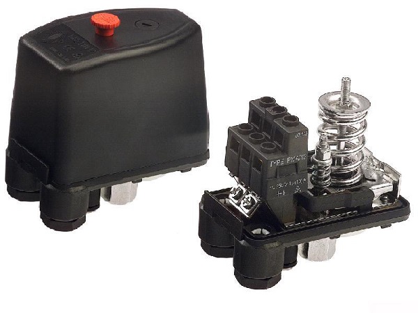
- Be sure to disconnect the device from the electrical outlet and remove the cover from the pressure switch.
- Removing the cover, you will see 2 bolts with springs. Big bolt Often denoted by the letter “P” with the signs “-” and “+” and is responsible for the upper pressure, at which the device will be turned off. To increase the level of air compression, turn the regulator in the direction of the “+” sign, and to decrease it - in the direction of the “-” sign.Initially, it is recommended to make a half turn of the screw in the right direction, then turn on the compressor and check the degree of pressure increase or decrease with a pressure gauge. Fix, at what indicators of the device engine shutdown will occur.
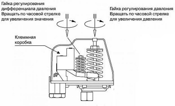
- Via small screw You can adjust the difference between the on and off thresholds. As mentioned above, it is not recommended that this interval exceed 2 bars. The longer the interval is, the less often the engine of the apparatus will start. In addition, the system will be significant and the differential pressure. Setting the difference on / off thresholds is done in the same way as setting the upper on threshold.
In addition, it is necessary configure gearboxif it is installed in the system. It is necessary to set such a compression level on the gearbox that corresponds to the working pressure of the pneumatic tool or equipment connected to the system.
/rating_off.png)