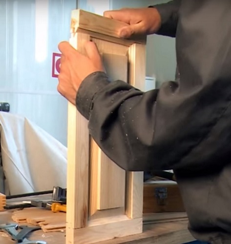
How to work a manual mill
Milling cutter is a unique tool with great functionality, which is an indispensable tool in the carpentry business. A hand mill can create various types of connections between wooden parts, make figured processing of edges, edges and layers of blanks, use it to select grooves and grooves, as well as for wood carving and metal engraving.
Content
General rules of work
Despite its ease of handling, the router is a traumatic tool if you use it without following simple rules.So, the basic rules for working with this unit are as follows.
- Sleeves of clothing should fit snugly to their hands. If you have long hair, you need to pick them up to prevent them from falling on the cutter and the subsequent winding.
- Before you begin, be sure to check network cable for damage to the insulation. Cord damage occurs at a time when the cable accidentally hits a mill that has not stopped yet. Insulation abrasions found must be insulated.
- Prepare the workplace so that it does not contain foreign objects (wrenches, screwdrivers, screws, etc.) that may fall under the working tool and damage it.
- Use only well sharpened tool (cutters). You can check the sharpness of the blade with your finger: for this you need to hold them on the blade at an angle of 90 degrees. If the edge is sharp, then you will feel a light hold of the skin by the sharp edges. Otherwise, the finger will slide off the blade easily.
- Before using the cutter with a thrust bearing, be sure to grease it with one drop of oil. The bearing should rotate easily and without delays.
- When installing the tooling in the collet, make sure that the cutter shank enters into it no less than 20 mm.
- Each time, when installing the cutter, remove carbon deposits and wood residues from its blades using a soft metal plate.
- Use special safety glasses. Well, if they are dustproof.
- Be sure to protect your respiratory system from the fine dust that is formed in abundance during milling, especially if the parts are made of laminated chipboard and MDF. As a defense, you can use a respirator or an ordinary medical mask purchased at a pharmacy.
- Always secure the workpiece to the table with clamps. Hold the workpiece with one hand during processing is prohibited.
- Right pick rotational speed spindle unit, depending on the diameter of the installed equipment. You should also pay attention to hardness of wood. The higher the hardness of the material, the slower the rotational speed should be set.
- The cutter in one pass should sink into the workpiece to a depth of no more than 3 mm.
- Before starting the processing of the workpiece, you should turn on the router and wait for the moment when the mill will gather the necessary momentum, and then proceed to the introduction of the mill into the wood.If you start milling at low revs or at the initial revolutions of the tool, then the cutting part of the tool will hit the workpiece, forming chips on it. In addition to damage to the parts, the router may bounce to the side and injure the operator.
- Keep the machine in such a way that you can see the rotating tooling and control its immersion in the material.
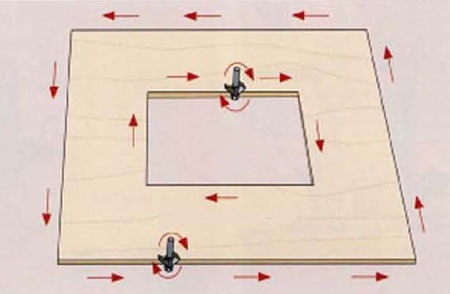
- As the mill rotates in the direction of the arrow, the mill movement should be directed in such a way that the tool blades move towards the materialas shown in the picture below.
- Milling cutter must be firmly held in the hands, but without undue pressure on the workpiece. Press it evenly and drive the unit smoothly, without jerks, throughout the entire trajectory of movement.
- If the work is carried out at low revs, and even for a long time, he needs cool occasionally. The unit should be started at maximum speed (idle) for 20-30 seconds so that the engine is well ventilated by the air flow created by the impeller mounted on its shaft.
- To stop milling, for example, the edges of the workpiece, you must first remove the mill from wood, and then turn off the unit.But when milling a deep groove, you must first stop the tool feed, turn it off, wait for the tool to stop completely and only then remove the cutter from the recess.
Preparation of the tool for work
The most important thing to do before starting milling is to set up the unit for a specific type of work, taking into account the properties of the material being processed and the type of tooling.
Speed selection
A milling cutter is a unit capable of developing very high spindle revolutions, from 8000 to 24000 rpm and more. The higher the speed of rotation of the tooling, the cleaner the surface to be treated. But you should be aware that exceeding the allowable speed for certain cutters can cause burning of the workpiece at the machining sites. Therefore, in addition to the rotation speed of the tool shank, it is necessary to take into account blade linear velocity. As a rule, the larger the diameter of the tooling, the faster the cutting edge of the tooling rotates. If you intend to use a snap-in of large diameter, then the spindle speed will need to be slightly reduced.
Below is a table, using which you can choose the optimal speed of rotation of the tool, depending on its diameter.

In addition, when choosing the tool rotation speed, the hardness of the material being processed should be taken into account. Milling of hard wood is required at a lower speed than recommended for a specific tool diameter.
You should also reduce the speed of the tool if you need cutting PVC, processing of Plexiglas and plastics. At high speeds, the plastic will begin to melt and adhere to the blade tooling. In each case, the rotational speed is selected experimentally.
Install the cutter
Before replacing the tool is necessary disconnect the router from the mains. Turning off the start button will not be enough. It is very important to unplug the power cord to prevent accidental engine starting.
The rigging changes as follows.
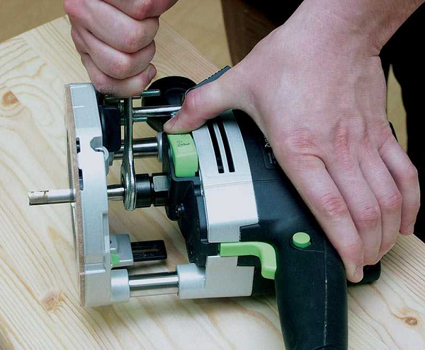
- Lay the machine on its side so that the button holding the spindle is on top.
- Press the button and turn the spindle until it engages with the retainer. After that, put the key on the collet nut and unscrew it. On some models of milling cutters this button may not be. In this case, you need 2 wrenches.The first key is put on the nut located on the spindle and acts as a retainer (if you rest it against the guide bar), and the second key is used to loosen the collet nut.
- After loosening the collet clamp, remove the bit shank from it.
- Next, insert a new snap-in, plunging its shank into the collet to a depth of at least 20 mm, that is, until it stops.
- Tighten the collet nut. Tighten the tool with sufficient force, but not enough to disrupt the thread.
- Unlock the spindle.
It should be remembered: the collet clamp nut cannot be tightened if it does not have a tooling. It will break it.
Setting the depth of processing
Almost all units for milling installed depth adjusters. Setting the depth of immersion tool is as follows:
- Place the unit on a flat surface, for example, on a table.
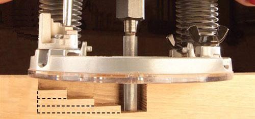
- Place the step of the turret stop (1), which has the smallest height, under the immersion limiter (2).

- Remove the lock from the depth stop by slightly unscrewing the screw (3) so that the stop (2) can move freely.
- Unlock the machine immersion mechanism. In some models of milling cutters, the engine is fixed on vertical rods using one rotating handle. There is also a considerable number of models of these units, where the drive is locked with a special pivot lever.
- Lower the motor down until the milling cutter touches the workpiece. This should be done slowly to avoid blades hitting the part.
- Next, you should again fix the engine on the rails.
- Lower the depth stop (2) onto the lowest step of the turret stop (1).
- Set the slider (4) on the “0” scale (6).
- Raise the limiter (2) to such a height that opposite to its slider (4) on the scale (6) is the dive value that you want to perform. For coarse adjustment, the limiter (2) is raised or lowered by hand. A more precise adjustment of the depth of immersion of the tool is made using the fine tuning mechanism (5).
- The position of the stopper (2) must be secured with the locking screw (3). Now you can unlock the immersion mechanism and lift the rig with the engine upwards.
As a resultif you lower the drive until the stop (2) touches the lowest step of the turret stop, you will get the maximum extension of the cutter relative to the base of the unit. This amount of immersion tool in the workpiece will be final, that is, to have the required depth.
If you want to make a deep groove that cannot be selected in a single pass, then you can use a turret support to gradually dip the tool into the workpiece.. To do this, move the highest step of the turret stop (1) under the depth limiter (2) and perform the milling. Next, substitute the next, lower stop under the limiter, and again make one pass with the tool. When the stop reaches the lowest stop, the required groove depth will be obtained. The following figure shows how the tool is gradually deepened into the workpiece, if you use a stop of a revolving type.
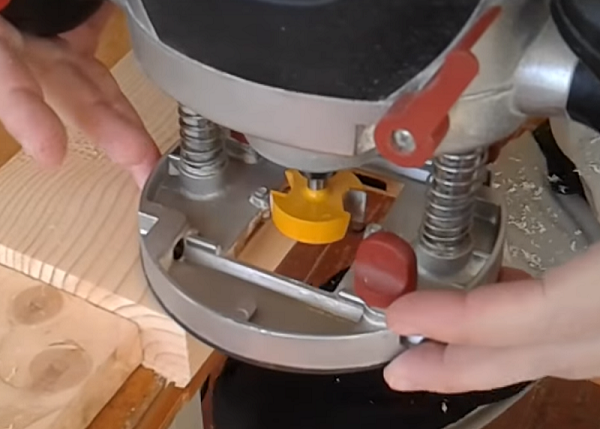
Edge processing
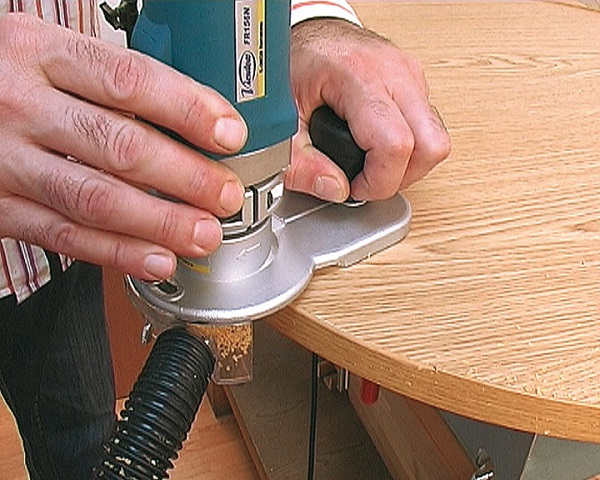
For processing edges and ends of the workpiece using special edge mills. They can be both straight and curly. Straight cutters are used for trimming (leveling) the edges of parts on a pattern (curvilinear) or on a ruler.For example, if you cut the chipboard with an electric jigsaw, then you cannot do without a router in this case. Edge after passing through the nail file turns out uneven and with small chips. To give her perfect geometry, do the following.
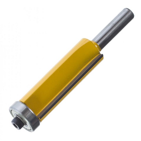
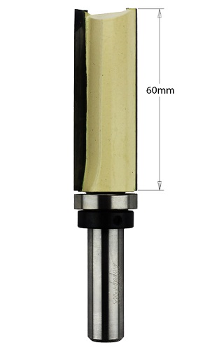
- Fasten a straight edge milling cutter in the router bit. This mill can have a bearing from below or in its upper part (near the shank).
- If the mill has a lower thrust bearing, the template is placed under the workpiece and both parts are pressed against the workbench with clamps. Conversely, the template is fixed on the workpiece with the upper bearing on the snap.
- When with lower bearing Place the bit on the edge of the workpiece and lower the cutter so that the thrust bearing is in the center of the template face, and the lower part of the blades extends about 2-3 mm onto the template. For cutters with upper bearing everything is done the other way around: the sole of the router is installed on the template under which the workpiece is laid. The milling cutter is lowered until the bearing reaches the center of the template, and the upper part of the blades will not capture it by 2-3 mm.
- Further, the slightly clamped workpiece is aligned with the template (you can use a rubber mallet) by the previously applied marking.
- After leveling, press the parts with clamps to the workbench.If you hold them loosely, they may shift due to strong vibration when the tool is working.
- Place the bit on the workpiece (template), without touching the details on the mill, turn on the unit and wait until it reaches full speed;
- Move the cutter smoothly to the beginning of the workpiece, so that the tool will cut into it and put the bearing on the template, and then cut along the entire edge.
For processing the ends of the blanks, you can use conventional submersible (vertical) milling machines. If it is required to remove PVC overhangs, the thickness of which can reach up to 4 mm, it will be more convenient to work with an edge milling machine, since it has compact dimensions and light weight.
Figured Face Mills mainly used for processing wood products and MDF. In this case, first, the workpiece is given a certain shape using a straight milling cutter. And after that, a tool with the required figure profile is inserted into the collet and the edges are machined in the usual way. Only as a template or guide for the bearing serves the aligned edge of the part.
When milling wooden parts, the direction of wood fibers should be considered.. If this is not done, chipping will occur at the corners of the workpieces or at the places where the longitudinal fibers become the end face when processing, for example, curvilinear parts. To avoid chipping, you should chalk out the “problem” places on the workpiece (Figure A). If you go through these sections of the mill in the usual way (against the arrow), then most often it will cause the formation of chips. Therefore, up to the “problem” zones, the tool is fed against the arrow, and at the fiber transition points, the direction is reversed (Figure C).
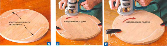
The same rule applies for processing corners of wooden blanks. First, the cutter must pass along the fibers along the arrow (through the corner), after which the facing continues in the usual way.
If milling of MDF facades (before plastic pasting them) or other products made from this material is performed, then you should not worry about chipping, since the material has a uniform structure.
Cutting holes
For cutting holes in wooden blanks you can use straight groove cutter. If the hole has a complex shape, then it is cut by a router according to a template prepared in advance using a copyrings. The latter is attached to the bit of the mill and, when the unit is in operation, it sets the tool movement in the desired direction.

So, to cut a hole in a wooden blank, you need to perform the following operations:
- fasten a straight groove cutter in the device collet;
- attach a copy sleeve to the router bit;
- put on the workbench the workpiece in which you want to make a hole;
- place small pieces of chipboard under the workpiece in order to slightly lift it above the table (this is required to exit the tool when cutting through the part);
- place the template with the already prepared hole on the workpiece and press both parts to the table with clamps;
- set the minimum amount of cutter outreach (about 3 mm) relative to the base of the device;
- turn on the router and gently lower it onto the template so that the router is gently inserted into the material;
- conduct milling around the perimeter of the template;
- lower the milling cutter by another 3 mm and repeat the above operation;
- continue to add 3 mm depth until the mill passes the workpiece through.
In the same way you can cut a round hole according to the appropriate pattern.But in order to cut a circle in the workpiece, there is a way much easier. The majority of models of milling cutters already includes circulator. It consists of a bar with an adjustable (pointed) screw on one side.
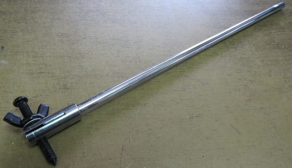
The bar is fixed to the base of the unit, and the pointed screw is inserted into the hole that serves as the center of the future circle. Next, you need to set the desired radius, taking into account the diameter of the cutter. The following figure shows how to correctly calculate the hole radius.
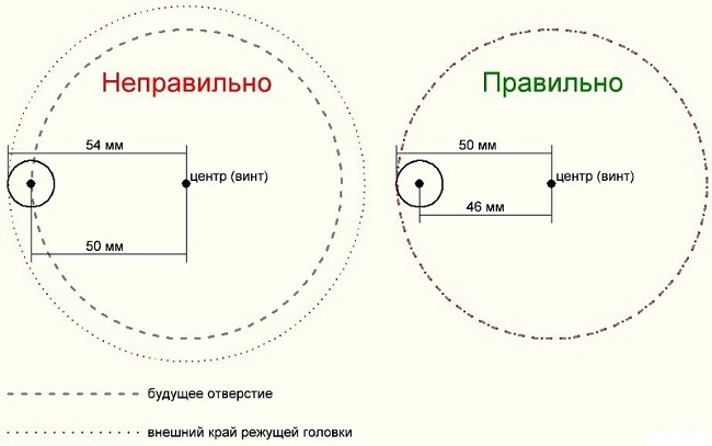
Milling is carried out in the usual way in several stages, each time deepening the tool by 3 mm.
Also mill can be drilled holes, for example, for installation of furniture hinges. This is done as follows.
- Clamp in the machine collet Forstner drill required diameter.
- Set the minimum spindle speed.
- Place the router on a flat surface.
- Lower the cutter so that the spike in its center does not reach the table surface 2-3 mm, and fix the drive on the guides.
- Next, lower the depth stop to any step of the turret stop and secure it with the locking screw.Thanks to the depth limiter, the milling cutter cannot fall below the required level.
- Remove the drive lock so that it can move freely up and down along the guides.
- On the workpiece should be the center of the future hole.
- Place the router bit on the workpiece and lower the mill in such a way that the spike located in its center exactly hits the intended place on the part.
- Raise the cutter slightly above the workpiece, turn on the unit and after a set of full rotations, smoothly begin to immerse the tool into the material until the depth gauge reaches the stop. At this drilling operation can be considered completed.
Before drilling on the workpiece, the same operation should be performed on some unnecessary piece of wood or laminated chipboard of the same thickness.
It is important that this blind hole has the necessary depth sufficient to install the furniture hinge cup in it, while there should not be any protuberances and through holes on the back of the part.
If you need to do through holethen the depth limiter is not necessary.For a “clean” cutter output on the back of the workpiece, drilling should be carried out in 2 stages. At the first stage, the cup drill is immersed in the workpiece until a small hole from the spike forms on its reverse side. Further, the workpiece is turned over, the spike of the drill is installed in the formed hole, and further drilling is carried out. Thus, the edges of the hole on both sides of the billet will be smooth and without chipping.
Insert locks and hinges
For insertion of hinges and locks in a wooden door, a number of special devices have been developed, on which a submersible milling cutter is installed.
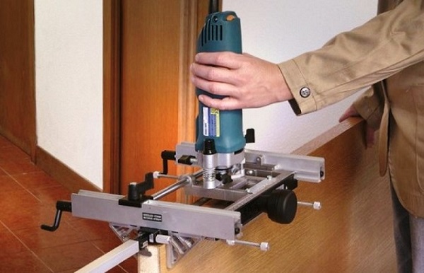
These devices are quite expensive, so the masters are trying to make them with their own hands. For example, inserting loops with a router without a template is a rather troublesome job. But this process is considerably simplified if you make a special simple template. How to do this, you can learn from this video.
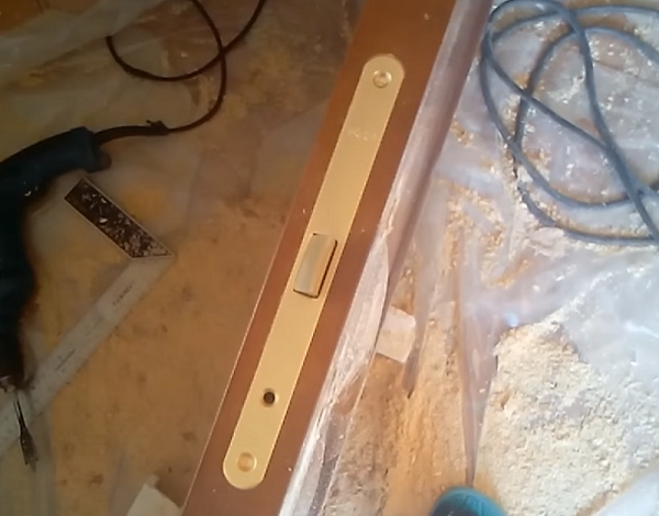
Inset locks in interior doors occurs in 2 stages: first, a wide groove under the front plate of the lock is formed, and then a deep groove under the lock body is selected. To form the seat of the lock body, you must perform the following steps.
- Take a straight groove cutter with a diameter of 0.5 mm larger than the lath of the lock.
- Set the depth of immersion on the mill to about 3 mm (depending on the plate thickness).
- Attach a parallel stop to the bottom of the machine.
- Attach the lock plate to the end of the door leaf and circle it with a pencil. Find the center edge of the door and draw a line through it (along the web).
- Install the router with an emphasis on the end of the door and center the router according to the marking, then fix the support in this position.
- Turn on the unit, immerse the cutter in the door leaf at the set depth and cut this area over the entire length. The result will be a wide and shallow groove under the front plate of the lock.
- Attaching the lock to the resulting groove, mark where the beginning and end of the deep groove will be.
- Next, you should choose a mill (straight groove) with such a diameter that it was slightly larger than the thickness of the body of the mortise lock. Also, its shank should be of sufficient length so that this cutter can make a groove 2-3 mm deep more than the height of the lock body.
- Clamp the tooling on the implement collet.
- Set on the unit the maximum immersion depth of the snap, sufficient to insert the lock body. This is done using the depth control.
- Turn on the unit and drill to the full depth set at the beginning of the marking. Repeat drilling along the entire length of this section, placing the holes as close as possible to each other.
- When the whole area has been worked out, raise the cutter slightly so that the upper part of the tooling edges is slightly out of the groove (1-2 mm) and perform milling by moving the unit back and forth. After several passes, the cutter can be deepened and again perform the above operation. As a result, you get a deep groove with a flat bottom and smooth walls.
Sampling of grooves and quarters
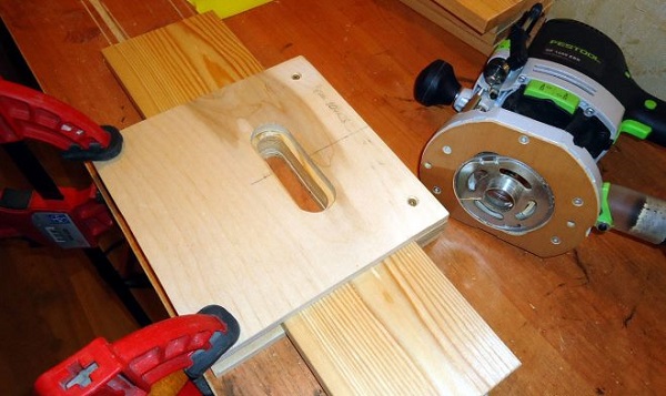
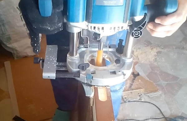
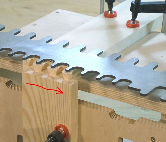
To select a groove on the surface of the workpiece or its edge (end), you can use a parallel stop, as in the case of door locks. But you can make a special device that facilitates the process, if you want to choose the grooves in a large number of identical parts from the tree. What it looks like slotting toolshown in the following image.
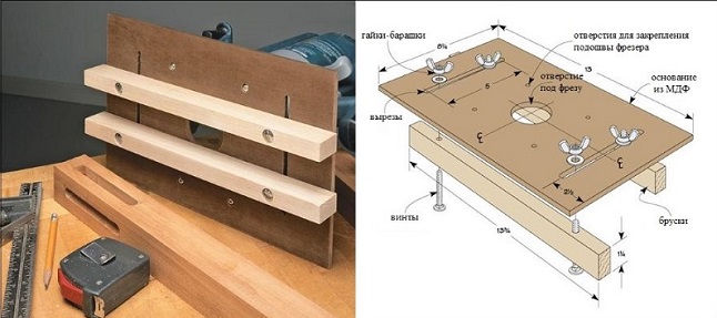
This device is configured simply:
- the unit is installed on the platform fixtures;
- the whole structure is superimposed on the workpiece;
- using parallel guides, a straight groove cutter is centered relative to the marking on the workpiece;
- after adjusting the depth of the tooling (usually requires several passes), grooves are made.
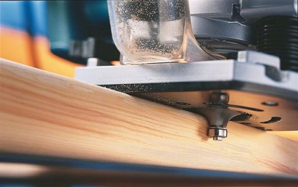
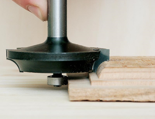
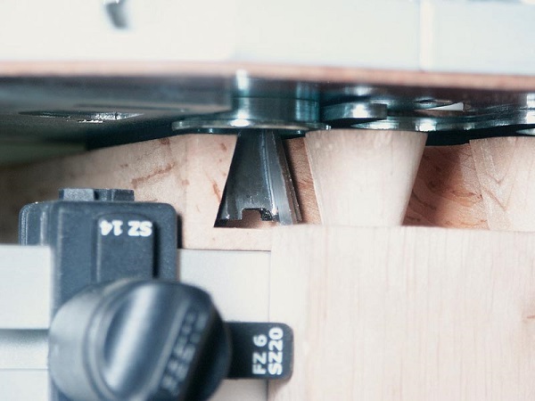
To select a quarter in a wooden blank, use groove cutter with bearing.
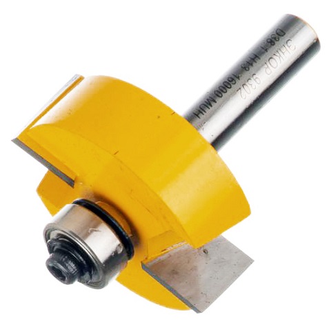
As a guide for tooling serves the edge (end) of the workpiece. The tool is clamped in the collet of the unit, after which the immersion height is set and a quarter is sampled in the usual way.
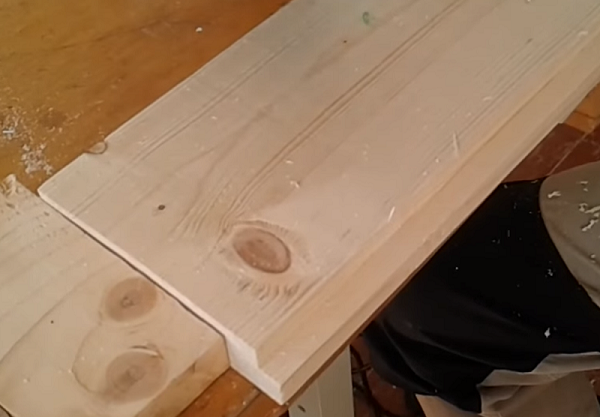
Choosing a quarter is not the only function of this snap. With it, you can select a groove along the edge of the workpiece and make a grooved board. The depth of the groove is regulated by changing the thrust bearings of different diameters.
For the manufacture of grooved boards in large volumes will need to mount the router to the table.
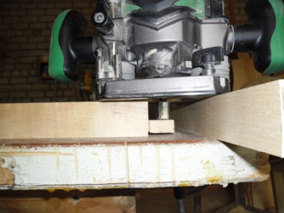
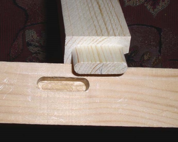
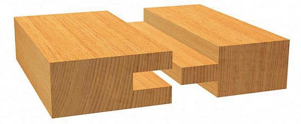
Thorn groove and dovetail
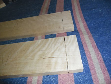
To create a thorn-groove connection, there are many complex devices. But if the production of wood products is not put on stream,That connection tongue and groove with the help of a hand mill can be made in a simple way.
- The part on which the spike will be cut should have a finished size. When making the markup, you should add the length of the spike to the length of the part. For example, for the legs of tables and chairs there will be enough a thorn length of 30-40 mm, and for doors - 55-70 mm. Using the square to make a markup on the edge of the workpiece.
- Take a hacksaw and make small cuts (this will be the shoulders of the spike).
- Prepare cutter “barrel””And secure it in the collet device. With its help spike connection will be created.
- Fix the workpiece on the workbench, and perpendicular to it secure the second part of the same thickness (will serve as a support for the mill router).
- Next, you need to set the amount of departure of the cutter relative to the site of the unit. If the spike is located exactly in the center of the workpiece, the tool overhang should be such that, after turning the part and the second pass, you get the spike thickness corresponding to the groove width. The width of the groove, in turn, depends on the diameter of the groove cutter. It is from this size that the calculation of the entire connection should begin.
- Once you have decided on the depth of the tool and set the limiter, you can begin to sample the spike. Turn on the unit and start milling the workpiece, but in stages, delving into the material by 3 mm each time.
- When the desired depth is reached, stop the machine and turn over the workpiece.
- Continue spike sampling using the method described above. As a result, you will get rectangular thorn. But, since the groove will have a rounding from the cutter around the edges, it will also be necessary to cut corners on the spike. This can be done with a knife or on a grinding machine.
How the groove is chosen has been discussed in detail above. If you want to make a thorn-groove along the entire length or width of the workpiece, then you will not need to round the corners of the spike.
To make a spike dovetail, use a special device.
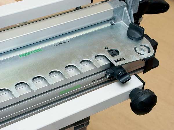
On the mill is installed grooving cutter “dovetail” tail, and also the copy sleeve having sides, for the best positioning in slots of a template.
After clamping the template and the workpiece is milled according to the general rules.
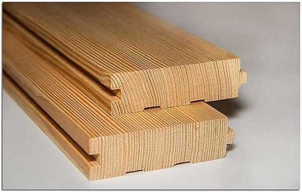
A tongue and groove joint is also used. in the manufacture of lining. Just to make the wall panel, you must have a set of 2 cutters. One cutter selects a groove on the edge of the part, and the other - makes a spike.
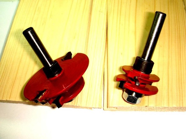
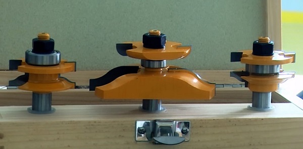
To make a file, the edge of which is a spike, and cut a groove in the frame of the facade, also use a set of cutters.
Metal work
Metal milling with a manual milling machine is performed in very rare cases, since this tool is not intended for these purposes. Sometimes it is used for stripping welds or rezsenkovki holes. It is also allowed to work with this tool for processing products from aluminum, copper, bronze and brass (for selecting grooves). A carbide grooving cutter is installed in the unit, and the part is milled in the usual way.
At the same time on the device you need to set the minimum spindle speed, and the depth of the snap tooling on one pass should be 0.5-1 mm.
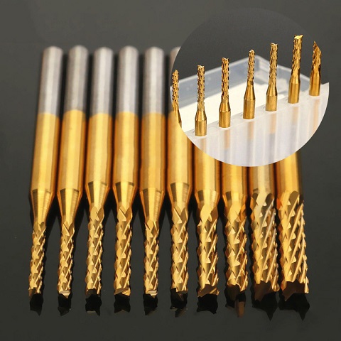
Sometimes a manual router is used for engraving patterns on planes from non-ferrous metals. In this case, the same templates and accessories are used as for woodworking, only special chucks are clamped in the router bit. engraving cutters.
Figured carving and crafts
Usually for shaped wood carving use grooving fillet and slot cutters. Wood carving hand milling is as follows:
- install a fillet groove cutter of small diameter into the unit;
- apply a drawing on the blank (you can use a stencil);
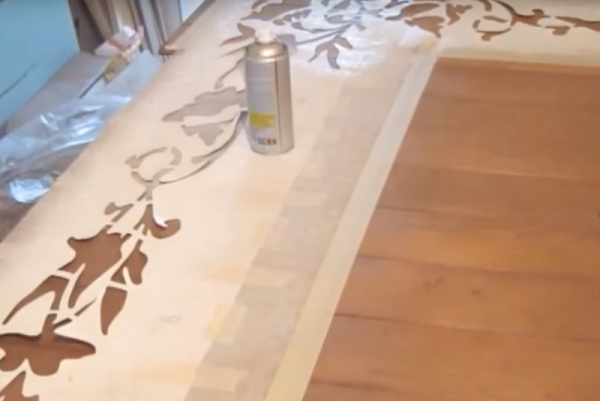
- circle the pattern with a black marker (not alcohol);
- pass along the drawn lines with a fillet mill, setting the immersion depth of 3-4 mm;
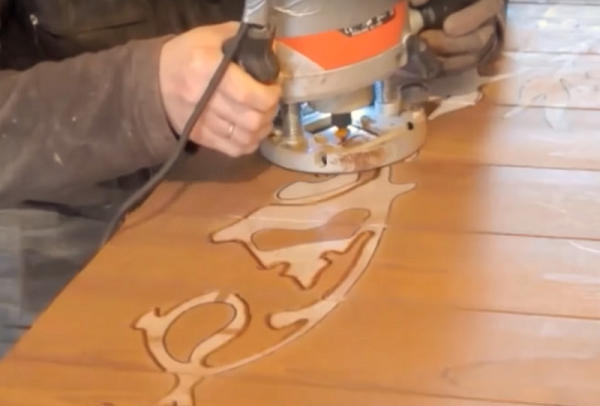
- Next, you should change the fillet milling cutter to a straight groove cutter and select the entire inside of the pattern;
- after milling, the resulting pattern should be sanded with sandpaper and varnished.
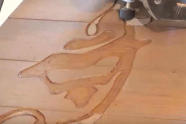
In the same way is done volumetric figure carving on the tree. Only the mill is selected not by the pattern, but by the background around it. Finishing ornament is already drilled or mini-drill (engraver).
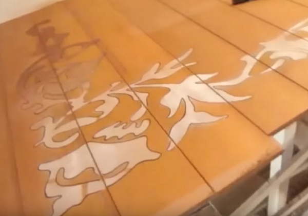
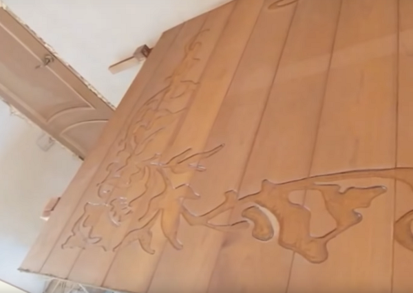
Also, with the help of a milling cutter, not only surface wood carving is performed, but also openwork through (slit) cutting plywood, thin furniture panels, MDF boards. The following figure shows a slotted pattern made by a router on plywood.
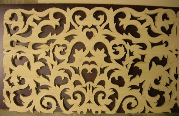
Processing of plywood is made with conventional cutters for wood.
Since plywood contains a certain amount of adhesive composition, the equipment must be cleaned of glue sticking to the blades more often than when processing wood.
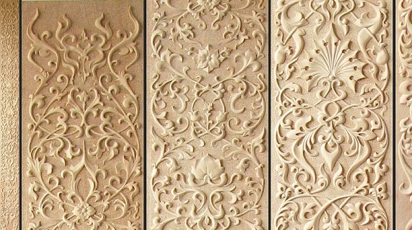
Using the above techniques, you can cut curly elements for gazebos, kitchen fronts, country furniture, etc.

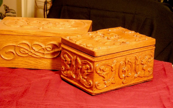
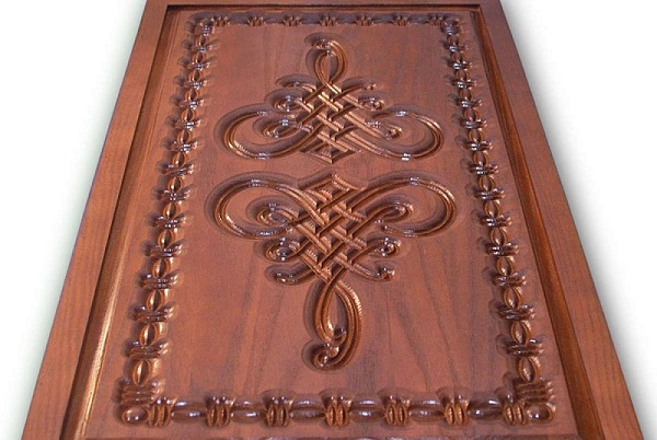
Different shapes can be decorated with carved wood wood crafts. For example, caskets, backgammon, make signs for various institutions.

Fraser also apply if required make balusters, decorated with twisted or straight thread. For milling rectilinear grooves, use a special device that is easy to do with your own hands.
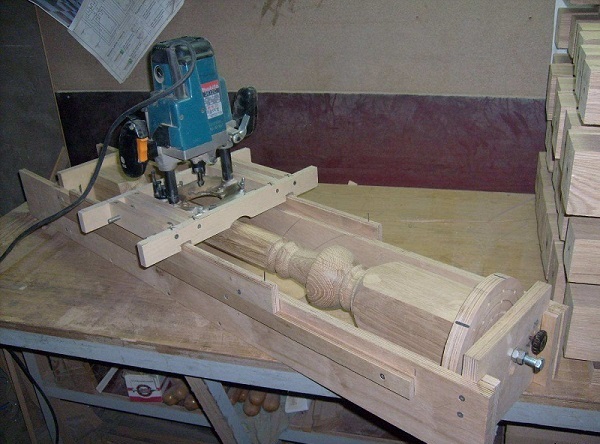
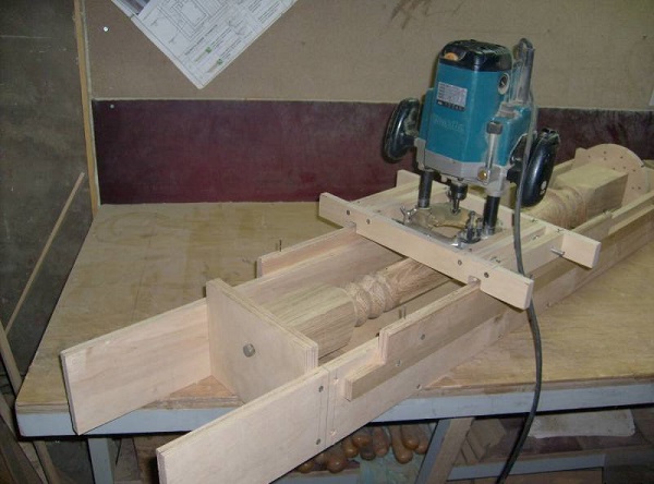
The process of milling balusters is as follows.
- The fillet grooving mill with the bearing is installed in the unit.
- So that the workpiece does not rotate, it is fixed with a screw. He must enter into one of the holes of the disk with a baluster attached to it.
- Further, the tool is lowered so that the thrust bearing is to the left or right of the workpiece and just below its center. But the cutter must be exactly in the center of the part.
- After positioning the tooling, the unit is turned on and a rounded groove is produced (the bearing drives the tool, repeating all forms of the baluster).
- In the next step, the router is diverted to the side, the fixing screw is released, and the disc is rotated so that the fixer hits the next hole.
- After fixing the workpiece again is a longitudinal sampling of the groove. After each pass of the cutter, it is necessary to rotate the workpiece by 1 step.
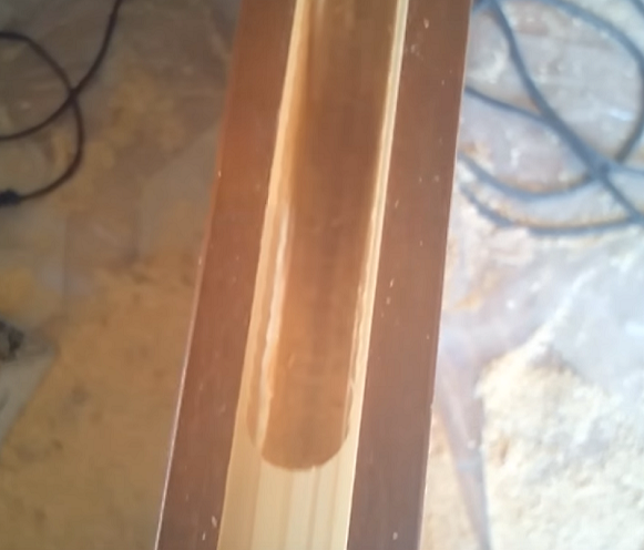
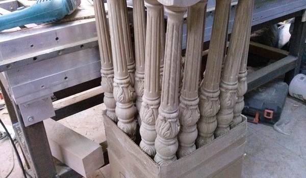
The following photo shows balusters with longitudinal grooves.
For the manufacture of twisted balusters need more complex adaptation.
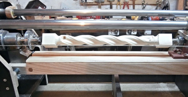
Twisted pattern is obtained by turning the workpiece during movement of the cutter on it. The rotation of the workpiece and the movement of the router on this machine is synchronized.
/rating_off.png)